High Precision Workflows
Precisión del Mapa
La precisión se puede definir como el grado o la cercanía con la que la información de un mapa coincide con los valores del mundo real. Por tanto, cuando nos referimos a la precisión, nos referimos a la calidad de los datos y al número de errores contenidos en un determinado conjunto de datos (Pascual 2011).
Precisión Relativa o Local
La precisión local o relativa se puede definir como el grado en que las distancias entre dos puntos en un mapa corresponden a las distancias reales entre esos puntos en el mundo real.
La precisión relativa es independiente de la ubicación del mapa en el mundo, por lo que un mapa puede tener una precisión relativa alta (en tamaño y forma), pero su posición en el mundo se puede cambiar (Figura 1).

Figura 1. Modelo que muestra una alta precisión relativa pero está fuera de lugar según su posición en el mundo real
Precisión absoluta o global
La precisión absoluta es la precisión de la reconstrucción en relación con su posición real en el planeta (Pix4D 2019). La Figura 2 muestra un modelo de precisión relativa y absoluta, ya que los puntos están colocados correctamente de acuerdo con su posición en el mundo real.

Figura 2. Modelo que muestra una alta precisión relativa y absoluta. Colocado correctamente de acuerdo con su posición en el mundo real
** Un nivel de precisión para cada proyecto**
Cada proyecto tiene necesidades específicas de precisión que se deben cumplir. Por ejemplo, evaluar el progreso en un sitio de construcción o medir un área afectada por un incendio no requiere el uso de GCP, ya que la precisión absoluta no afectará el proceso de toma de decisiones. Por otro lado, hay tareas en las que la precisión es fundamental, por ejemplo, evaluaciones de cumplimiento de proyectos y levantamiento de títulos de propiedad, que requieren una mayor precisión relativa y absoluta.
Que esperar
En términos generales, se puede esperar que la precisión relativa sea del orden de 1 a 3 veces el GSD promedio para el conjunto de datos. Y en cuanto a la precisión absoluta, se debe considerar que depende de la unidad GPS montada en el UAV pero la precisión horizontal de un GPS estándar suele estar en el rango de 2 a 6 metros y la precisión vertical entre 3 y 4 veces la precisión horizontal.
Cuando se utiliza GCP, la precisión absoluta se puede mejorar a 2,5 veces GSD para la precisión horizontal y 4 veces la GSD para la precisión vertical (Madawalagama 2016).
A un GSD de 1 cm, la precisión es igual a la del RTK GNSS, y está dentro de las escalas de 1:200 según los estándares de precisión de mapeo NSDI y FGDC durante condiciones subóptimas (Barry 2013).
Aspectos que impactan la precisión del mapa
Clima
Las condiciones climáticas tienen un impacto directo en los resultados de la fotogrametría, por lo que es importante considerar la cobertura de nubes, la velocidad del viento, la humedad, la altitud del sol y otros factores que influyen en la estabilidad del UAV y la iluminación del terreno.
Cámaras
Los sensores más grandes y mejores producen menos ruido e imágenes más claramente enfocadas. También tenga en cuenta que las cámaras con obturador «rolling shutter» producen imágenes distorsionadas cuando la UAV se está moviendo, por lo que para las actividades de mapeo, se recomiendan las cámaras con obturador mecánico o global.
Altitud del vuelo
Cuanto mayor sea la altitud de vuelo, mayor será la huella de la imagen y el GSD. Con el GSD más grande resultante, la precisión disminuirá ya que habrá menos detalles en las características reconocibles. Cuando se requiere un GSD más pequeño, se recomienda una altitud de 3 a 4 veces la altura del punto más alto.
Velocidad del vuelo
La velocidad de vuelo tiene un efecto especial en las cámaras equipadas con obturador «rolling shutter», mientras que las equipadas con obturador global o mecánico tienden a reducir este efecto. Los UAV equipados con sistemas de posicionamiento RTK también se ven afectados por la velocidad, pero deteniendo la UAV en cada foto tomada, puede obtener una muy buena precisión. Si, en cambio, se está moviendo durante cada toma de fotos, la precisión estará limitada por dos factores: la velocidad a la que se está moviendo multiplicada por los incrementos de 1 segundo de RTK (Mather 2020).
Referencias
Barry, P., & Coakley, R. «Accuracy of UAV photogrammetry compared with Network RTK GPS.» Baseline Surveys. 2013. http://uav.ie/PDF/Accuracy_UAV_compare_RTK_GPS.pdf (accessed 10 13, 2020).
Drone Deploy. How Do I Use Ground Control Points?: A guide to using ground control points with drone mapping software. 5 8, 2017. https://www.dronedeploy.com/blog/what-are-ground-control-points-gcps/ (último acceso el 9 del 7, 2020).
Madawalagama, S.L., Munasinghe, N., Dampegama, S.D.P.J. and Samarakoon, L. «Low-cost aerial mapping with consumer grade.» 37th Asian Conference on Remote Sensing. Colombo, Sri Lanka, 2016.
Mather, Stephen. OpenDroneMap. 30 de Marzo de 2020. https://community.opendronemap.org/t/the-accuracy-of-webodm-using-rtk-uavs/3937 (último acceso el 12 del 10, 2020).
Pascual, Manuel S. GIS Lounge: GIS Data: A Look at Accuracy, Precision, and Types of Errors. 11 6, 2011. https://www.gislounge.com/gis-data-a-look-at-accuracy-precision-and-types-of-errors/ (último acceso el 09 del 07, 2020).
Pix4D. «What is accuracy in an aerial mapping project?» Pix4D. 25 de 05 de 2019. https://www.pix4d.com/blog/accuracy-aerial-mapping (último acceso el 13 del 10, 2020).
Ground Control Points
Overview
Ground control points are useful for correcting distortions in the data and referencing the data to know coordinate systems.
A Ground Control Point (GCP) is a position measurement made on the ground, typically using a high precision GPS. (Toffanin 2019)
Ground control points can be set existing structures like pavement corners, lines on a parking lot or contrasting color floor tiles, otherwise can be set using targets placed on the ground.
Targets can be purchased or build with an ample variety of materials ranging from bucket lids to floor tiles.
Recommended practices for GCP setting
Keep ground control points visible for all camera locations. Consider the expected ground sampling distance, illumination, vegetation, buildings and all the existing obstacles.
Procure an evenly horizontal distribution of the GCPs within the project, covering high and low elevations. A minimum of 5 GCP works for most of the jobs, and for larger projects 8 – 10 are sufficient. Locate some points near the corners and others in the center, considering that GCP spacing should be larger than the image footprint so that you can’t see more than one GCP in a single image.
In order to ensure each GCP are found in at least 5 images, separate the points 10 to 30 meters from the perimeter of the project. This distance is dependent of the overlapping, so increasing overlapping should reduce the required distance from the perimeter.
GCP file format
The format of the GCP file is simple.
The first line should contain the name of the projection used for the geo coordinates. This can be specified either as a PROJ string (e.g.
+proj=utm +zone=10 +ellps=WGS84 +datum=WGS84 +units=m +no_defs), EPSG code (e.g.EPSG:4326) or as aWGS84 UTM <zone>[N|S]value (eg.WGS84 UTM 16N)Subsequent lines are the X, Y & Z coordinates, your associated pixels, the image filename and optional extra fields, separated by tabs or spaces:
Avoid setting elevation values to «NaN» to indicate no value. This can cause processing failures. Instead use 0.0
Similarly decreasing the no. of digits after the decimal place for geo_x and geo_y can also reduce processing failures.
The 7th column (optional) typically contains the label of the GCP.
GCP file format:
<projection>
geo_x geo_y geo_z im_x im_y image_name [gcp_name] [extra1] [extra2]
...
Example:
+proj=utm +zone=10 +ellps=WGS84 +datum=WGS84 +units=m +no_defs
544256.7 5320919.9 5 3044 2622 IMG_0525.jpg
544157.7 5320899.2 5 4193 1552 IMG_0585.jpg
544033.4 5320876.0 5 1606 2763 IMG_0690.jpg
If you supply a GCP file called gcp_list.txt then ODM will automatically detect it. If it has another name you can specify using --gcp <path>. If you have a gcp file and want to do georeferencing with exif instead, then you can specify --use-exif. If you have high precision GPS measurements in your images (RTK) and want to use that information along with a gcp file, you can specify --force-gps.
This post has some information about placing Ground Control Targets before a flight, but if you already have images, you can find your own points in the images post facto. It’s important that you find high-contrast objects that are found in at least 3 photos, and that you find a minimum of 5 objects.
Sharp corners are good picks for GCPs. You should also place/find the GCPs evenly around your survey area.
The gcp_list.txt file must be created in the base of your project folder.
For good results your file should have a minimum of 15 lines after the header (5 points with 3 images to each point).
User Interfaces
You can use one of two user interfaces for creating GCP files:
POSM GCPi
The POSM GCPi is loaded by default on WebODM. An example is available at the WebODM Demo. To use this with known ground control XYZ values, one would do the following:
Create a GCP list that only includes gcp name (this is the label that will be seen in the GCP interface), x, y, and z, with a header with a proj4 string of your GCPs (make sure they are in a planar coordinate system, such as UTM. It should look something like this:
+proj=utm +zone=37 +south +ellps=WGS84 +datum=WGS84 +units=m +no_defs
gcp01 529356.250827686 9251137.5643209 8.465
gcp02 530203.125367657 9250140.80991621 15.781
gcp03 530292.136003818 9250745.02372435 11.977
gcp04 530203.125367657 9250140.80991621 15.781
gcp05 530292.136003818 9250745.02372435 11.977
Then one can load this GCP list into the interface, load the images, and place each of the GCPs in the image.
GCP Editor Pro
This app needs to be installed separately or can be loaded as a WebODM plugin from https://github.com/uav4geo/GCPEditorPro
Create a CSV file that includes the gcp name, northing, easting and elevation.
GCP Label,Northing,Easting,Elevation
gcp01,529356.250827686,9251137.5643209,8.465
gcp02,530203.125367657,9250140.80991621,15.781
...
Then import the CSV from the main screen and type +proj=utm +zone=37 +south +ellps=WGS84 +datum=WGS84 +units=m +no_defs in the EPSG/PROJ box.
The following screen will display a map from where to select the GCPs to tag and import the respective images.
Referencias
Toffanin, Piero. Open Drone Map: The Missing Guide. MasseranoLabs LLC, 2019.
Image Geolocation Files
By default ODM will use the GPS information embedded in the images, if it is available. Sometimes images do not contain GPS information, or a user wishes to override the information with more accurate data (such as RTK).
Starting from ODM 2.0 people can supply an image geolocation file (geo) for this purpose.
The format of the image geolocation file is simple.
The first line should contain the name of the projection used for the geo coordinates. This can be specified either as a PROJ string (e.g.
+proj=utm +zone=10 +ellps=WGS84 +datum=WGS84 +units=m +no_defs), EPSG code (e.g.EPSG:4326) or as aWGS84 UTM <zone>[N|S]value (eg.WGS84 UTM 16N)Subsequent lines are the image filename, X, Y & Z (optional) coordinates, the camera angles (optional, currently used only for radiometric calibration) and the horizontal/vertical accuracy (optional):
Camera angles can be set to
0if they are not available.The 10th column (optional) can contain extra fields, such as a label.
File format:
<projection>
image_name geo_x geo_y [geo_z] [yaw (degrees)] [pitch (degrees)] [roll (degrees)] [horz accuracy (meters)] [vert accuracy (meters)] [extras...]
...
Example:
EPSG:4326
DJI_0028.JPG    -91.9942096111111   46.84252125 198.609
DJI_0032.JPG    -91.9938293055556   46.8424584444444    198.609
If you supply a file called geo.txt then ODM will automatically detect it. If it has another name you can specify using --geo <path>.
The geo.txt file must be created in the base of your project folder or when using WebODM, uploaded with the raw jpg or tif input files.
Improving relative accuracy
Georeferencing by default is done using GPS (GNSS) or GCPs (if provided).
Starting from ODM 3.0.2 people can supply a reference alignment file to georeference the program outputs. The reconstruction will be initially performed using GPS/GCPs and will subsequently be aligned to the reference model via a linear scaling/rotation/shift operation.
If you supply a file called align.laz, align.las or align.tif (single band GeoTIFF DEM) then ODM will automatically detect it and attempt to align outputs to this reference model. If it has another name you can specify using --align <path>.
The alignment file must be created in the base of your project folder. The base folder is usually where you have stored your images. If you are using WebODM or NodeODM, then upload the align file with your images. If resizing your images in WebODM, use an align.laz or align.las file instead of a tif.
Multi-temporal Datasets
When previously mapped sites need revisited, OpenDroneMap can align multiple versions of a dataset through time by using a prior point cloud or digital elevation model. As the prior point cloud seems to provide better results, that is the approach we will review here.
Workflow for multi-temporal datasets:
Process your original data. This step doesn’t require a ground control point file, but use one if absolute accuracy is a project requirement
Download the Point Cloud from your first processed dataset as an LAZ file type (default). Rename the point cloud to align.laz
Include that LAZ file with each of your subsequent processing. If you are using command line ODM, include it in the images directory. If uploading, simply upload with your raw images for processing
Check your log. It should include a line near the top that indicates it has set align to a path value, something like this:
[INFO]    Initializing ODM 3.5.3 - Tue Oct 15 05:01:43  2024
[INFO]    ==============
[INFO]    3d_tiles: False
[INFO]    align: /var/www/data/bc14fa2c-ba5c-4b85-99b0-0b7ff715b210/gcp/align.laz
[INFO]    auto_boundary: True
Output example for aligned datasets:

Animated gif comparing two separately processed, but aligned digital surface models.
Plugin Time-SIFT
The script at contrib/time-sift in the ODM repository does Time-SIFT processing with ODM. Time-SIFT is a method for multi-temporal analysis without the need to co-registrate the data.
D. Feurer, F. Vinatier, Joining multi-epoch archival aerial images in a single SfM block allows 3-D change detection with almost exclusively image information, ISPRS Journal of Photogrammetry and Remote Sensing, Volume 146, 2018, Pages 495-506, ISSN 0924-2716, doi: 10.1016/j.isprsjprs.2018.10.016 (https://doi.org/10.1016/j.isprsjprs.2018.10.016)
Requirements
ODM ! :-)
subprocess
json
os
shutil
pathlib
sys
argparse
textwrap
Usage
Provided example
Download or clone this repo to get example data.
Then execute
python Timesift_odm.py datasets --end-with odm_filterpoints
It should make the Time-SIFT processing on the downloaded example data, stopping after the filtered dense clouds step.
In the destination dir, you should obtain new directories, 0_before and 1_after at the same level as the time-sift-block directory. These new directories contain all the results natively co-registered.
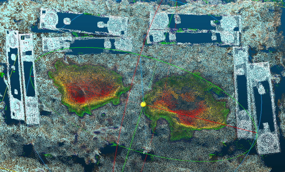
You can then use CloudCompare to compute distance between the datasets/0_before/odm_filterpoints/point_cloud.ply and the datasets/1_after/odm_filterpoints point_cloud.ply and obtain this image showing the difference between the two 3D surfaces. Here, two soil samples were excavated as can be seen on the image below.

Your own data
In your dataset directory (usually datasets, but you can have chosen another name) you have to prepare a Time-SIFT project directory (default name : time-sift-block, can be tuned via a parameter) that contains : * images/ : a subdirectory with all images of all epochs. This directory name is fixed as it is the one expected by ODM *
images_epochs.txt : a file that has the same format as the file used for the split and merge ODM function. This file name can be tuned via a parameter.
The images_epochs.txt file has two columns, the first column contains image names and the second contains the epoch name as follows
DSC_0368.JPG 0_before
DSC_0369.JPG 0_before
DSC_0370.JPG 0_before
DSC_0389.JPG 1_after
DSC_0390.JPG 1_after
DSC_0391.JPG 1_after
Your directory, before running the script, should look like this :
$PWD/datasets/
└── time-sift-block/
    ├── images/
    └── images_epochs.txt
At the end of the script you obtain a directory by epoch (at the same level as the Time-SIFT project directory). Each directory is processed with images of each epoch and all results are natively co-registered due to the initial sfm step done with all images.
$PWD/datasets/
├── 0_before/
├── 1_after/
└── time-sift-block/
Aligning Large Datasets
When attempting to process very large datasets it may very well be the case that one needs to devide a large set of images into smaller more manageable chunks for ease of processing.This process however, may introduce some uncertainty with respect to the alignment of all the processed outputs.To make sure that all point clouds and terrain/suface models are seamlessly alighn in preparation for merging we follow the simple techniques outlined below.
Workflow for aligning large datasets:
#.Split the full compliment of images into manageable chunks. E.g. If you have flown and collected a total of 1000 images but you know your processor cannot handle all these images at once, you may want to devide these images into four sets of submodels with 250 images each. #.Process the first dataset with theDigital Surface Model (DSM) option enabled. #.Download the DSM from first dataseta in its raw-tiff format and rename it to “align.tif” #.Load the second dataset together with the align.tif #.Process the second dataset (including the align.tif file) #.Repeat until all submodels have been processed.
Aprende a editar y ayuda a mejorar esta página!