Tutorial
Selanjutnya kamu akan melihat instruksi untuk beberapa penggunaan umum.
Membuat Ortofoto Kualitas Tinggi
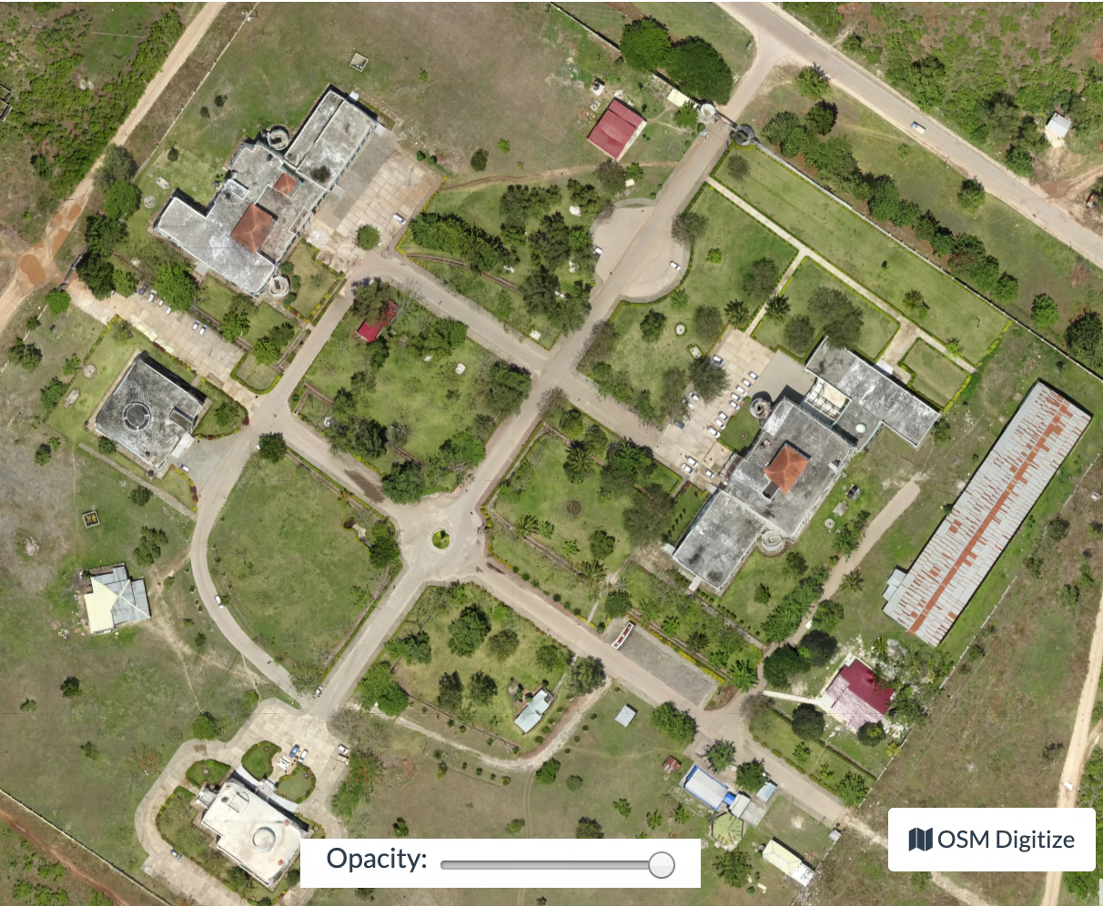
Tanpa penyesuaian parameter apa pun, ODM memilih kompromi yang baik antara kualitas, kecepatan, dan penggunaan memori. Jika Anda ingin mendapatkan hasil berkualitas lebih tinggi, Anda perlu menyesuaikan beberapa parameter:
--orthophoto-resolutionadalah resolusi orthophoto dalam cm/pixel. Turunkan nilai ini untuk mendapatkan hasil resolusi yang lebih tinggi.
--mesh-sizeshould be increased to300000-600000and--mesh-octree-depthshould be increased to10-11in urban areas to recreate better buildings / roofs.
Membuat Model Elevasi Digital
By default ODM does not create digital elevation models (DEMs). To create a digital terrain model, make sure to pass the --dtm flag. To create a digital surface model, be sure to pass the --dsm flag.
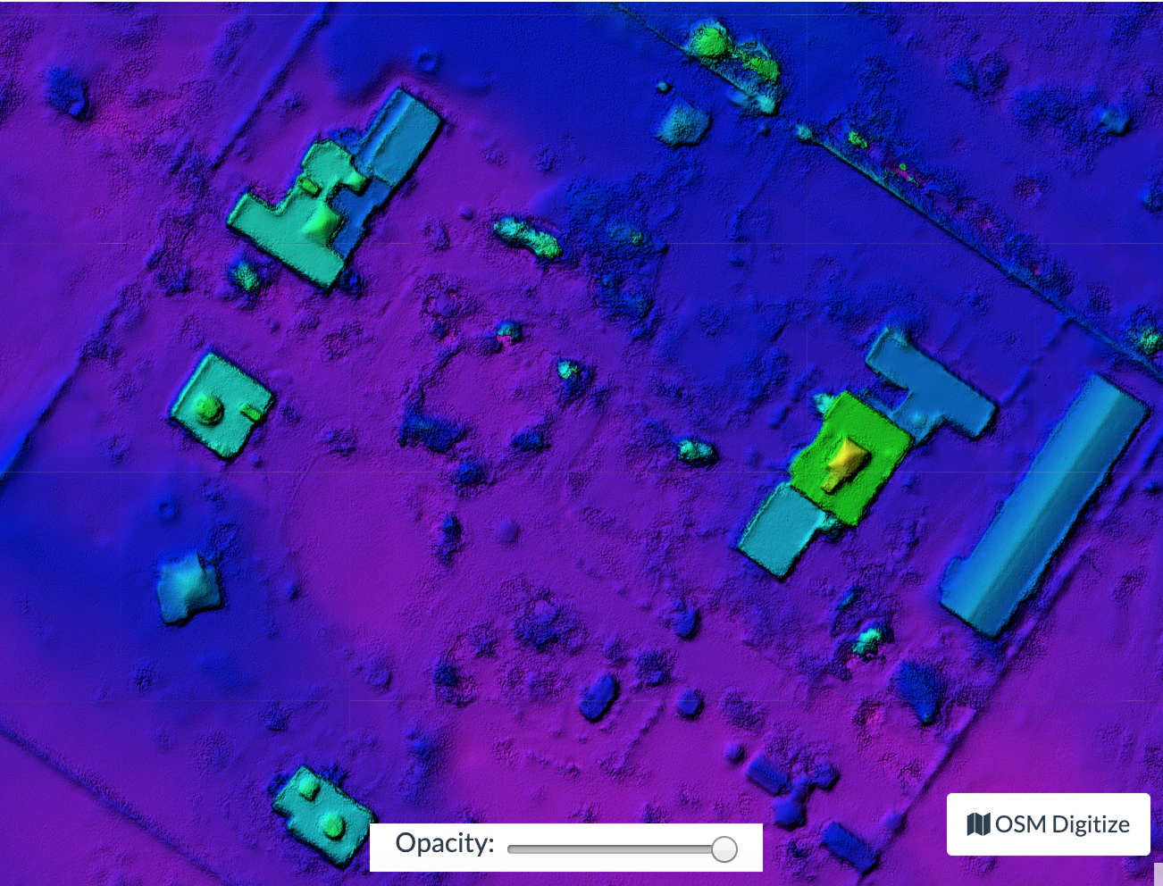
For DTM generation, a Simple Morphological Filter (smrf) is used to classify points in ground vs. non-ground and only the ground points are used. The smrf filter can be controlled via several parameters:
--smrf-scalarscaling value. Increase this parameter for terrains with lots of height variation.
--smrf-slopeslope parameter, which is a measure of "slope tolerance". Increase this parameter for terrains with lots of height variation. Should be set to something higher than 0.1 and not higher than 1.2.
--smrf-thresholdelevation threshold. Set this parameter to the minimum height (in meters) that you expect non-ground objects to be.
--smrf-windowwindow radius parameter (in meters) that corresponds to the size of the largest feature (building, trees, etc.) to be removed. Should be set to a value higher than 10.
Changing these options can affect the result of DTMs significantly. The best source to read to understand how the parameters affect the output is to read the original paper An improved simple morphological filter for the terrain classification of airborne LIDAR data (PDF freely available).
Overall the --smrf-threshold option has the biggest impact on results.
SMRF is good at avoiding Type I errors (small number of ground points mistakenly classified as non-ground) but only "acceptable" at avoiding Type II errors (large number non-ground points mistakenly classified as ground). This needs to be taken in consideration when generating DTMs that are meant to be used visually, since objects mistaken for ground look like artifacts in the final DTM.
Dua parameter penting lainnya memengaruhi pembuatan DEM:
`` --dem-resolusi '' yang menetapkan resolusi keluaran raster DEM (cm / piksel)
--dem-gapfill-stepswhich determines the number of progressive DEM layers to use. For urban scenes increasing this value to 4-5 can help produce better interpolation results in the areas that are left empty by the SMRF filter.
Contoh bagaimana menghasilkan DRM:
docker run -ti --rm -v /my/project:/datasets/code <my_odm_image> --project-path /datasets --dtm --dem-resolution 2 --smrf-threshold 0.4 --smrf-window 24
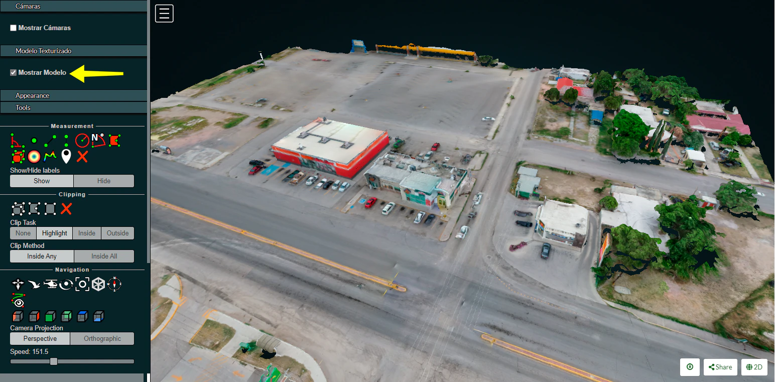
Using Potree 3D viewer module on OpenDroneMap Desktop
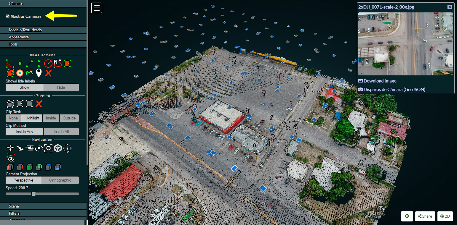
Cameras
Activate this function to display camera positions.
You can also click in the camera icon to display single images in a frame on the upper right corner. A click on the image frame toggles into full screen mode.
Within the image frame there are links to download the image and the GeoJSON camera file.
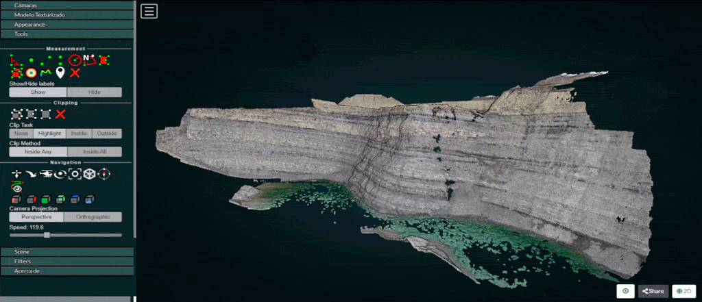
Textured model
Activate this function to show load the textured model. Depending on the file size and connection speed, it may take several seconds to load.
Appearance
Point budget
For both appearance and performance purposes, the point budget on the scene can be managed. Some old and less capable machines would benefit from a 500,000 point budget while most mid-range specs machine are capable of handling 1 to 2 million point budget.
A 5 to 7 million point budget produces a smooth point cloud 3d model, but may result in a high resource demanding process.
Default point budget value is set to 1,000,000.
Field of view
In order to control model elements to be included within the scene the field of view can be adjusted. Default value is set to 60 degrees.
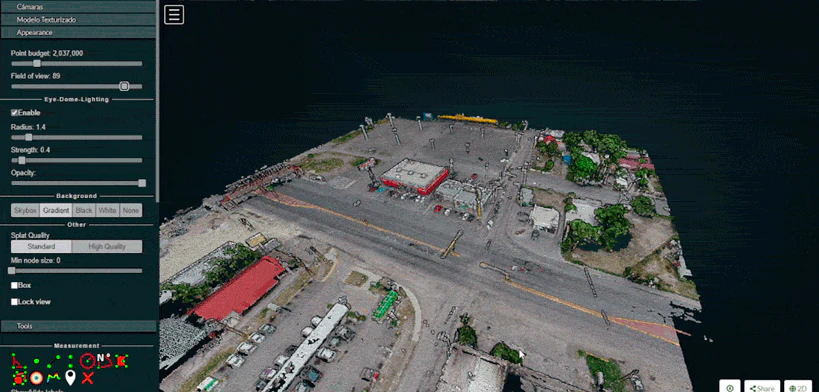
Eye Dome-lighting
The Potree Point Cloud 3d viewer module can implement eye dome-lighting, a lighting model that accentuates the shapes of objects.
Eye Dome-lighting group objects, shade their outlines and enhances depth perception in scientific visualization images. It is useful for recognition and measurement of structures within a model. It can be modified by adjusting Radius, Strength and Opacity.
By default, Eye Dome-Lighting is enabled on Potree 3D viewer, but it can be disabled by clicking on the enable option.
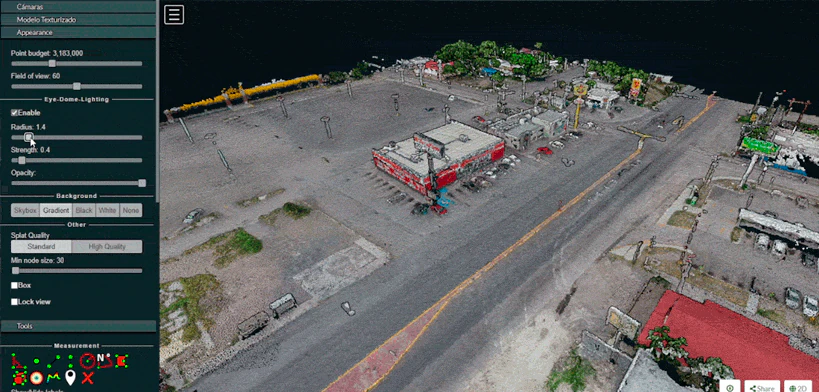
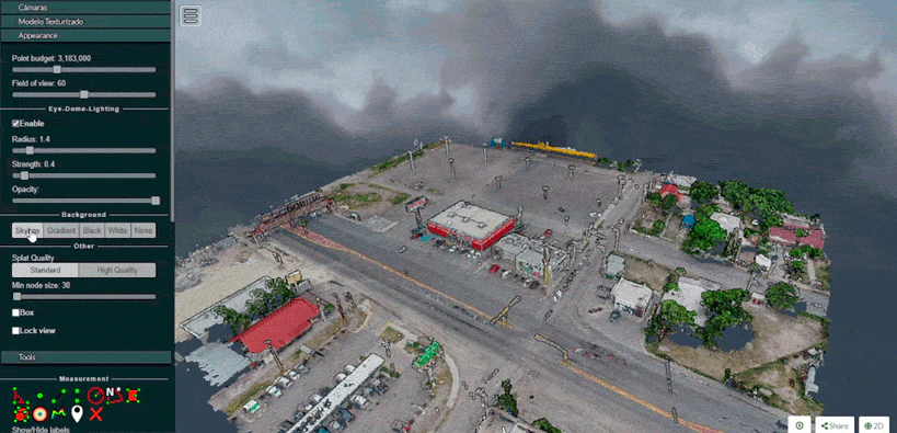
Background
Potree 3D viewer background can be modified. Available options are Skybox / Gradient / Black / White / None
Other
Splat Quality = Splat quality can be adjusted to standard or high quality, to improve the appearance of the model.
Min node size = Min node size option will impact the point density of the nodes represented.
Box = Display the boxes of the nodes.
Lock view = Lock the point cloud view, preventing to load or unload points to the model.
Tools
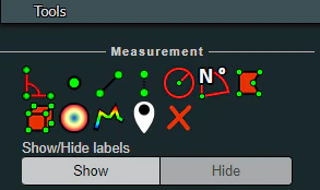
Measurement
Potree 3D viewer module provides several tools for measurement. This tool set consist of 12 elements. It also has controls for showing or hiding the resulting measurement labels.
Measurements are performed by left clicking on the desired points and for some tools right clicking is needed in order to terminate the process.
Angle
This tool measures the tridimensional angle formed by the lines connecting 3 points. To start a measurement, click on the angle icon, then left click on 3 point and the process will be automatically ended. Further information can also be obtained from selecting this element under the scene section.
Point
This tool highlights a selected point and display its XYZ coordinate. To start a measurement, click on the point icon, then click on the desired point and the process will be automatically ended. Further information can also be obtained from selecting this element under the scene section.
Distance
This tool measures the tridimensional distance of the lines connecting a series of points. To start a measurement, click on the distance icon and start clicking on the desired points (two or more). Right click to finish measurement. Further information such as Total length can also be obtained from selecting this element under the scene section.
Height
This tool measures the height or vertical distance between two points. To start a measurement, click on the height icon and then click on the desired two points. The process will be automatically ended. Further information can also be obtained from selecting this element under the scene section.
Circle
This tool measures the radius of a circle formed by three points. To start a measurement, click on the circle icon and then click on the desired two points. The process will be automatically ended. Further information such as Circumference can also be obtained from selecting this element under the scene section.
Azimuth
This tool measures the azimuthal angle of a line. This line is formed by two points selected by the user, the angle is measured in degrees, clockwise from 0 to 360 and starting from the geographical north. To start a measurement, click on the azimuth icon and then click on the desired two points. The process will be automatically ended. Further information can also be obtained from selecting this element under the scene section.
Area
This tool measures the horizontal area formed by a polygon. To start a measurement, click on the area icon and start clicking on the points forming the desired polygon (three or more). Right click to finish measurement. Further information can also be obtained from selecting this element under the scene section.
Volume (cube)
This tool measures the volume formed by a cube. To start a measurement, click on the volume (cube) icon and click on the model to place the cube. It is possible relocate, redimension and rotate the cube using the displayed handlers. Right click to finish measurement. Further information can also be obtained from selecting this element under the scene section.
Volume (sphere)
This tool measures the volume formed by a sphere. To start a measurement, click on the volume (sphere) icon and click on the model to place the sphere. It is possible relocate, redimension and rotate the sphere using the displayed handlers. Right click to finish measurement. Further information can also be obtained from selecting this element under the scene section.
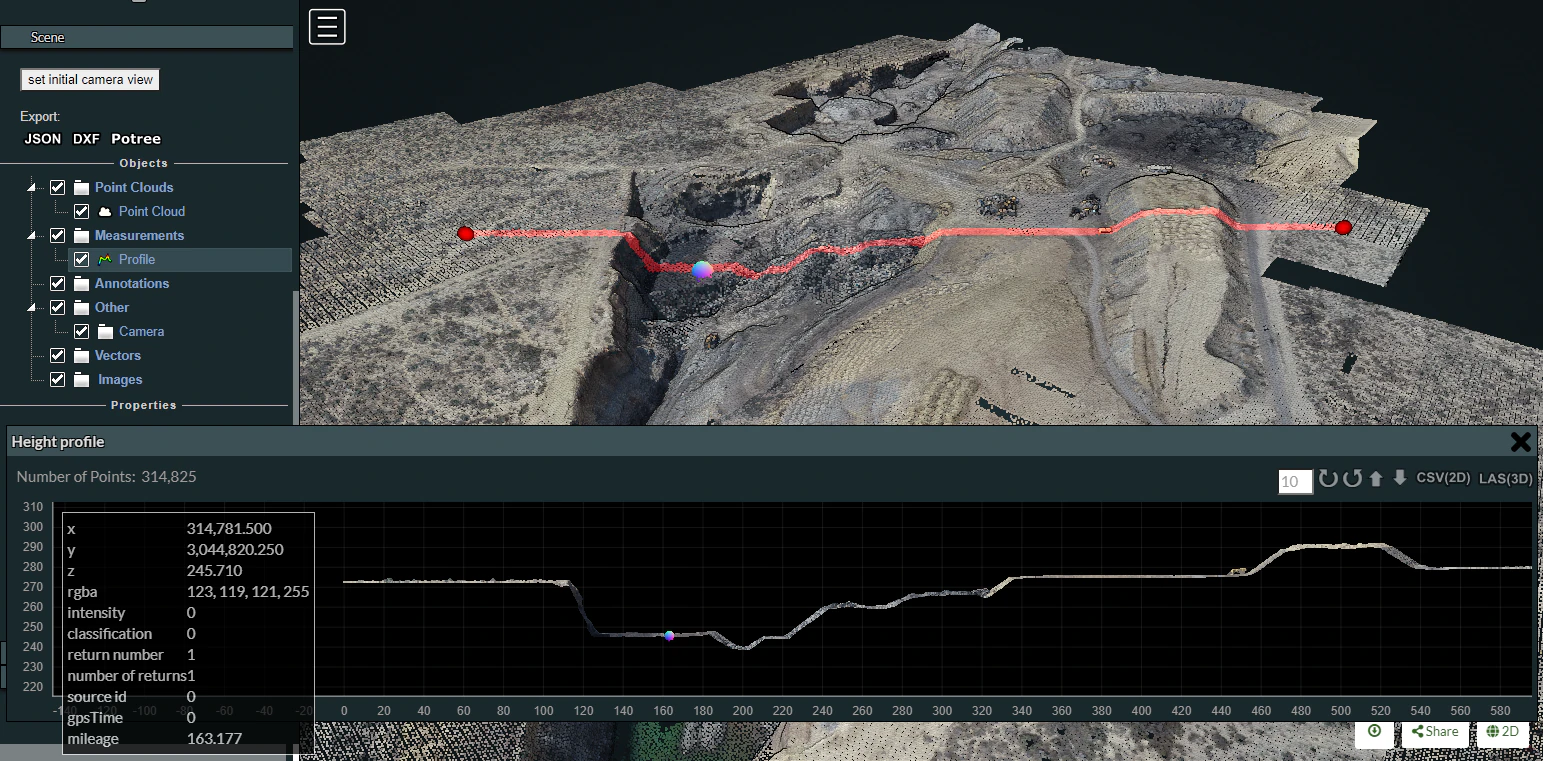
Height profile
This tool creates a height profile formed by a line on the model. To start a measurement, click on the Height profile icon and then form a line on the model by clicking on the desired points (two or more). Right click to finish measurement. Further information and options, such as "Show 2d Profile", can also been obtained from selecting this element under the scene section.
Annotation
This tool creates an annotation label on a highlighted point on the model. To start a measurement, click on the annotation icon and then click on the desired point. The process will be automatically ended. To edit the annotation, select this element under the scene section, then edit Title and Description.
Remove measurements
This tool removes all measurements on the model. To remove all measurement, click on the "Remove measurements" icon.
Clipping
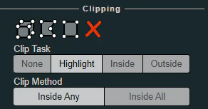
Point cloud can be clipped by selecting an area. Clipping options include None / Highlight / Inside / Outside
To clip a point cloud, click on the volume clip icon, place the cube on the model and relocate, redimension and rotate to contain the desired area. Highlight is set by default as the clipping method. If display only the points contained within the cube click on "Inside", otherwise click on "Outside".
To remove the clipping volume or polygons click on the "Remove all measurements" icon.
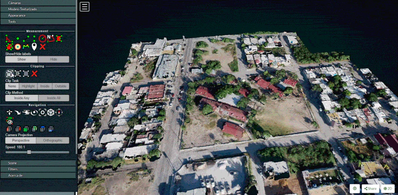
Navigation
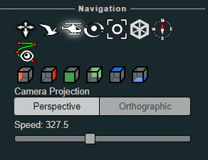
Potree 3D viewer have 4 Navigation controls which define its behavior.
Earth Control
Earth control navigated as anchored to the ground. Mouse left button moves the model horizontally, mouse wheel controls zoom and right button orbits the model.
Fly control
Fly control moves the camera as in birds eye using the keyboard. Keys "W" and "S" moves forward and backwards, respectively and in the direction of the camera, while "A" and "D" moves left and right respectively. Also, the "R" and "F" keys moves the camera up and down. The mouse left button changes the direction of the camera, mouse wheel controls zoom, and right button moves the camera in the XYZ axis.
The speed for these movements can be controlled using the sliding control.
Helicopter control
Helicopter control moves the camera as in an aircraft using the keyboard. Keys "W" and "S" moves forward and backwards, respectively restricted in a horizontal plane, while "A" and "D" moves left and right respectively. Also, the "R" and "F" keys moves the camera up and down. The mouse left button changes the direction of the camera, mouse wheel controls zoom, and right button moves the model in the XY axis.
The speed for these movements can be controlled using the sliding control.
Orbit Control
Orbit Control is the default navigation behavior. The mouse left button orbits the model, the wheel controls zoom and the right button moves the model in the XYZ axis.
Full extent
Full extent button restores the model view.
Navigation cube
Navigation cube displays a wireframe cube containing the model.
Compass
Compass button displays a compass on the upper right corner.
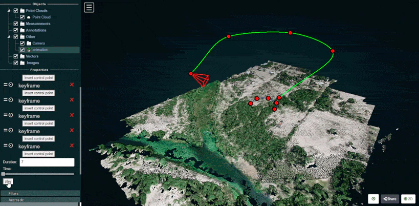
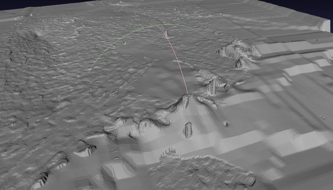
Camera animation
The camera animation button creates a camera animation path. Position of the camera is defined by the points on the green line while the points in the blue line are the location towards the camera is intended to be facing.
To create an animation, adjust the points for the camera locations and camera direction, then select the camera element under the Scene section to create more point, change animation speed or play the animation.
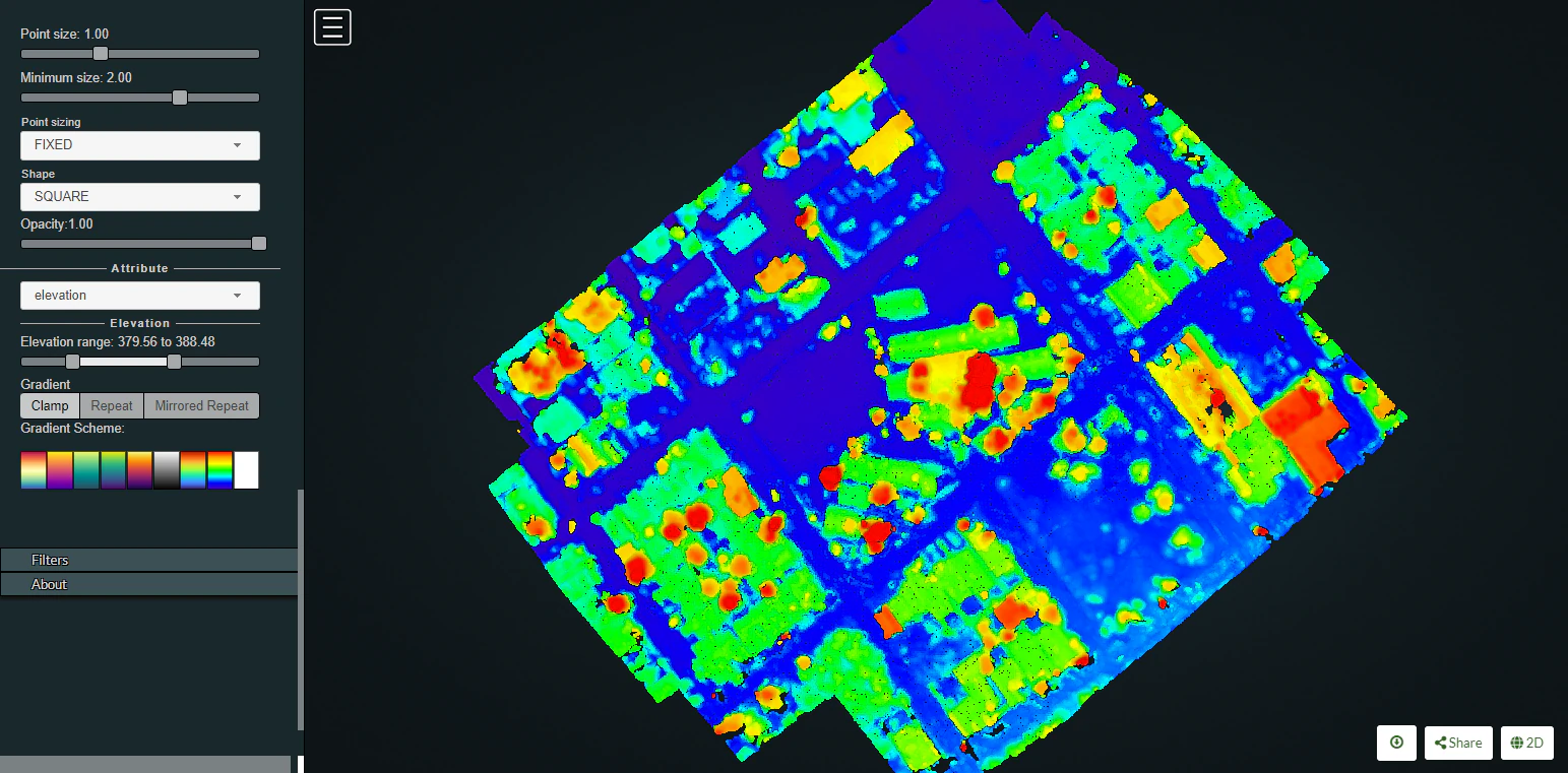
Scene
The Scene section displays a file tree containing all the scene elements. Elements are arranged in six groups, which are Point clouds / Measurements / Annotations / Other / Vector / Images
Each element under these groups can be selected to get further information or to control its properties.
For instance, point clouds properties can be modified to show elevation and also the color ramp cam be customized.
Measuring stockpile volume
Fieldwork planning
Weather conditions modify illumination and thus impact the photography results. Best results are obtained with evenly overcast or clear skies. Also look for low wind speeds that allow the camera to remain stable during the data collection process. In order to avoid shadows which on one side of the stockpile can obstruct feature detection and lessen the number of resulting points, always prefer the flights during the midday, when the sun is at the nadir so everything is consistently illuminated. Also ensure that your naked eye horizontal visibility distance is congruent with the planned flight distances for the specific project, so image quality is not adversely impacted by dust, fog, smoke, volcanic ash or pollution.
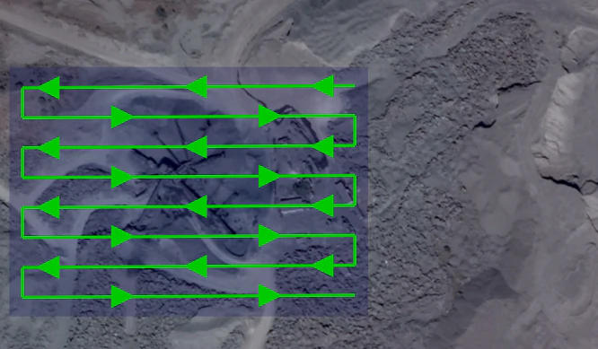
Flight pattern
Most stockpile measurement jobs does not require a crosshatch pattern or angled gimbal as the resting angle of stockpile materials allows the camera to capture the entire stockpile sides. Only some special cases where erosion or machinery operations causes steep angles on the faces of the stockpile would benefit of the crosshatch flight pattern and angled camera gimbal but consider that these additional recognized features come at a cost, (in field labor and processing time) and the resulting improvements are sometimes negligible.
In most of the cases a lawn mower flight pattern is capable of producing highly accurate stockpile models.
Recommended overlap would be between 75% and 80% with a sidelap in the order of 65% to 70%. It is also recommended to slightly increase overlap and sidelap as the flight height is increased.
Flight height
Flight height can be influenced by different camera models, but in a general way and in order to ensure a balance between image quality and flight optimization, it is recommended to be executed at heights 3 to 4 times the tallest stockpile height. So for a 10 meter stockpile, images can be captured at a height of 40 meters. As the flight height is increased, it is also recommended to increase overlap, so for a 40 meter height flight you can set a 65% sidelap and 75% overlap, but for a planned height of 80 meters a 70% sidelap and 80% overlap allowing features to be recognized and properly processed.
GCPs
To achieve accuracy levels better than 3%, the use of GCP’s is advised. Typically 5 distributed GCP are sufficient to ensure accurate results. When placing or measuring GCP, equipment accuracy should be greater than the GSD. Survey grade GNSS and total stations are intended to provide the required millimetric accuracy.
For further information on the use of GCPs, please refer to the Ground Control Points section.
Processing parameters
A highly accurate model can be achieved using OpenDroneMap Desktop high resolution predefined settings. Then you can further adjust some parameters as necessary.
If using ODM, these this reference values can help you configure the process settings.
--dsm: true
--dem-resolution 2.0
--orthophoto-resolution 1.0
--feature-quality high
--pc-quality high
Measuring
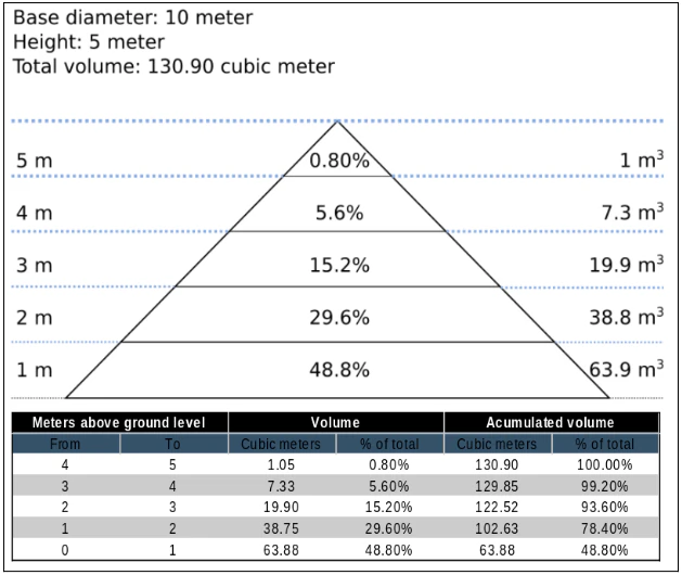
As almost 50% of the material will be found in the first 20% of the stockpile height, special care should be taken in adequately defining the base plane.
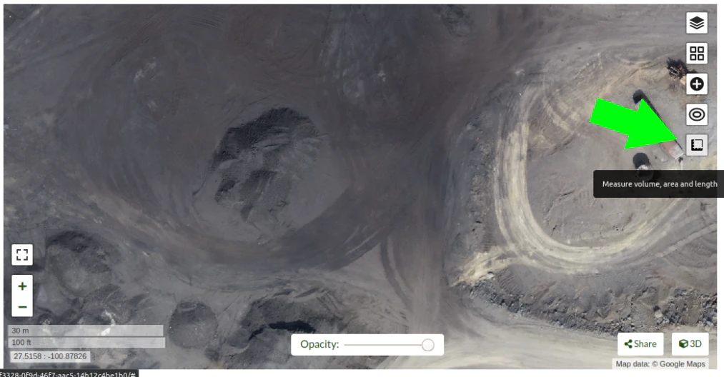
In OpenDroneMap Desktop Dashboard, clic on "view map" to start a 2D view of your project.
Once in the 2D map view, clic on the "Measure volume, area and length" button.
then clic on "Create a new measurement"
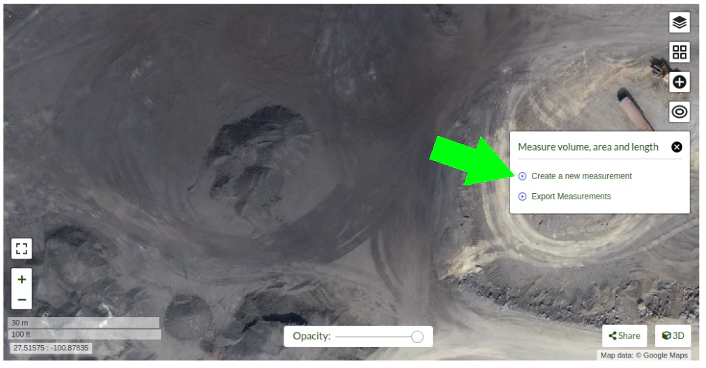
Start placing the points to define the stockpile base plane
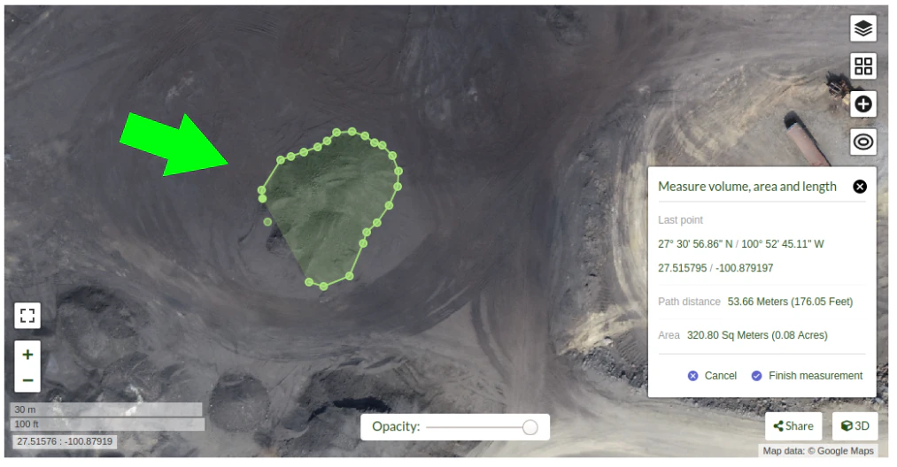
Clic on "Finish measurement" to finish the process.
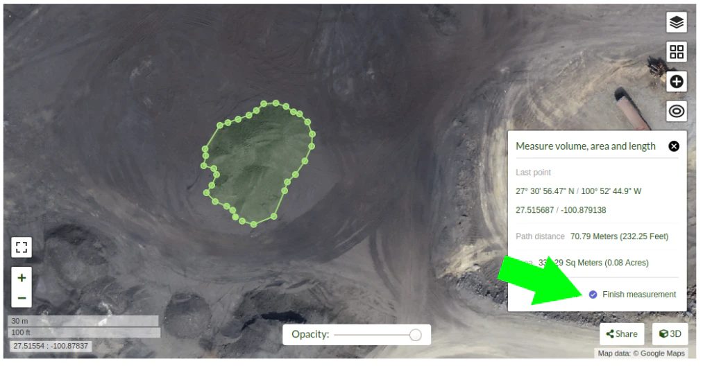
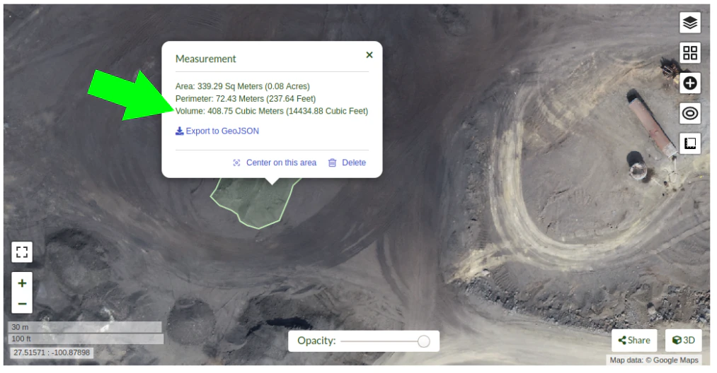
Dialog box will show the message "Computing ..." for a few seconds, and after the computing is finished the volume measurement value will be displayed.
If you are using the command line OpenDroneMap you can use the dsm files to measure the stockpile volumes using other programs.
Also consider that once the limits of the stockpile are set in software like QGis, you will find there are some ways to determine the base plane. So for isolated stockpiles which boundaries are mostly visible, a linear approach can be used. While for stockpiles set in slopes or in bins, the base plane is better defined by the lowest point. Creation of a triangulated 3D surface to define the base plane is advised for large stockpiles. This is also valid for stockpiles paced on irregular surfaces.
Expected accuracy
For carefully planned and executed projects, and specially when GSD is less than 1 cm, the expected accuracy should be in the range of 1% to 2%. The resulting accuracy is comparable to the commercially available photogrammetry software and the obtained using survey grade GNSS equipment.
Menggunakan Docker
Since many users employ docker to deploy OpenDroneMap, it can be useful to understand some basic commands in order to interrogate the docker instances when things go wrong, or we are curious about what is happening. Docker is a containerized environment intended, among other things, to make it easier to deploy software independent of the local environment. In this way, it is similar to virtual machines.
Beberapa perintah sederhana dapat membuat pengalaman docker kami jauh lebih baik.
Daftar Mesin Docker
Kita bisa mulai dengan membuat daftar mesin docker yang tersedia di mesin saat ini yang kita jalankan sebagai berikut:
> docker ps
CONTAINER ID        IMAGE                  COMMAND                  CREATED             STATUS              PORTS                    NAMES
2518817537ce        opendronemap/odm       "bash"                   36 hours ago        Up 36 hours                                  zen_wright
1cdc7fadf688        opendronemap/nodeodm   "/usr/bin/nodejs /va…"   37 hours ago        Up 37 hours         0.0.0.0:3000->3000/tcp   flamboyant_dhawan
Jika kita ingin melihat mesin yang mungkin tidak berjalan tetapi masih ada, kita dapat menambahkan tanda -a:
> docker ps -a
CONTAINER ID        IMAGE                  COMMAND                  CREATED             STATUS                    PORTS                    NAMES
2518817537ce        opendronemap/odm       "bash"                   36 hours ago        Up 36 hours                                        zen_wright
1cdc7fadf688        opendronemap/nodeodm   "/usr/bin/nodejs /va…"   37 hours ago        Up 37 hours               0.0.0.0:3000->3000/tcp   flamboyant_dhawan
cd7b9585b8f6        opendronemap/odm       "bash"                   3 days ago          Exited (1) 37 hours ago                            nostalgic_lederberg
e31010c00b9a        opendronemap/odm       "python /code/run.py…"   3 days ago          Exited (2) 3 days ago                              suspicious_kepler
c44e0d0b8448        opendronemap/nodeodm   "/usr/bin/nodejs /va…"   3 days ago          Exited (0) 37 hours ago                            wonderful_burnell
Mengakses catatan server
Using either the CONTAINER ID or the name, we can access any logs available on the machine as follows:
> docker logs 2518817537ce
This is likely to be unwieldy large, but we can use a pipe | character and other tools to extract just what we need from the logs. For example we can move through the log slowly using the more command:
> docker logs 2518817537ce | more
[INFO]    DTM is turned on, automatically turning on point cloud classification
[INFO]    Initializing OpenDroneMap app - Mon Sep 23 01:30:33  2019
[INFO]    ==============
[INFO]    build_overviews: False
[INFO]    camera_lens: auto
[INFO]    crop: 3
[INFO]    debug: False
[INFO]    dem_decimation: 1
[INFO]    dem_euclidean_map: False
...
Pressing Enter or Space, arrow keys or Page Up or Page Down keys will now help us navigate through the logs. The lower case letter Q will let us escape back to the command line.
We can also extract just the end of the logs using the tail command as follows:
> docker logs 2518817537ce | tail -5
[INFO]    Cropping /datasets/code/odm_orthophoto/odm_orthophoto.tif
[INFO]    running gdalwarp -cutline /datasets/code/odm_georeferencing/odm_georeferenced_model.bounds.gpkg -crop_to_cutline -co NUM_THREADS=8 -co BIGTIFF=IF_SAFER -co BLOCKYSIZE=512 -co COMPRESS=DEFLATE -co BLOCKXSIZE=512 -co TILED=YES -co PREDICTOR=2 /datasets/code/odm_orthophoto/odm_orthophoto.original.tif /datasets/code/odm_orthophoto/odm_orthophoto.tif --config GDAL_CACHEMAX 48.95%
Using band 4 of source image as alpha.
Creating output file that is 111567P x 137473L.
Processing input file /datasets/code/odm_orthophoto/odm_orthophoto.original.tif.
Nilai -5 berarti meminta perintah tail untuk hanya memberikan 5 baris log terakhir saja.
perintah konsol akses ke server
Terkadang kita perlu mengamati lebih teliti dalam mengeksplorasi proses di OpenDroneMap. Untuk itu, kita dapat memanfaatkan akses langsung konsol ke server. Kita gunakan docker exec untuk jalankan perintah bash konsol di server yang kita inginkanin sebagai berikut:
> docker exec -ti 2518817537ce bash
root@2518817537ce:/code#
Sekarang kita telah masuk ke docker dan dapat mengeksplorasi mesin.
Membersihkan setelah Docker
Docker has a lamentable use of space and by default does not clean up excess data and machines when processes are complete. This can be advantageous if we need to access a process that has since terminated, but carries the burden of using increasing amounts of storage over time. Maciej Łebkowski has an excellent overview of how to manage excess disk usage in docker.
Menggunakan ODM dari lokasi bandwidth rendah
Untuk apa ini dan untuk siapa?
Melalui repo Ivan Gayton.
OpenDroneMap can’t always be effectively set up locally—it takes a fairly powerful machine to process large datasets—so a cloud machine can sometimes be the answer for people in the field. However, bandwidth is a problem in many low-income settings. This constraint can’t be solved completely, but the following method does a reasonable job of reducing the bandwidth needed to process drone imagery datasets on the cloud from African locations.
Here we present a tricky but workable process to create an OpenDroneMap cloud machine (not CloudODM, mind you, just a cloud-based instance of ODM that you run from the command line) and use it to remotely process large photo sets. It requires familiarity with Unix command line use, ssh, a Digital Ocean account (Amazon AWS would work as well, possibly with slight differences in the setup), and a moderate level of general computer literacy. If you aren’t fairly computer-savvy and willing to fuss with a slightly tricky setup, CloudODM is what you should be looking at.
The whole process is mostly targeted at someone flying substantial missions in an African or similar location looking to process data ASAP while still in a field setting. Therefore it emphasizes a workflow intended to reduce bandwidth/data transfer, rather than just the simplest way of running ODM.
Langkah-langkah
Instal
Create a Digital Ocean droplet with at least 4GB of RAM. That’ll cost about $20/month. Less than 4GB of RAM and the install will probably fail. When we actually run the ODM process we’ll resize it to a much larger—and more expensive—cloud machine, but between runs you can downsize it between runs to the second-cheapest droplet which costs only $10/month (the cheapest droplet, at $5/month, comes with such a small drive that you can’t downsize back to it).
Should be an Ubuntu 18.04 instance to ensure dependency compatibility
Create a user with sudo privileges. Digital Ocean’s insanely good documentation can help you figure this out. In our case we set up a user called
odm, so connecting to it is via the commandssh odm@xxx.xxx.xxx.xxx(where the x’s stand for the IPv4 address of your server). If you want to follow this example closely, do use the usernameodm; then your install path will be/home/odm/ODM/and will match all of the examples in this document.Go ahead and execute
sudo apt updateandsudo apt upgradeto ensure your server isn’t dangerously without updates. Make sure to stay with Ubuntu 18.04.
Download and install ODM on it from the ODM Github with the following commands:
git pull https://github.com/OpenDroneMap/ODM.git
cd ODM
bash configure.sh install
If you do this from the default home folder of your user (i.e.
odm) the path to the install will be/home/odm/ODM(abbreviated as~/ODM/).There are some environmental variables that need to be set. Open the ~/.bashrc file on your machine and add the following 3 lines at the end (From the ODM github). The file can be opened with
nano ~/.bashrc(or whatever text editor you use in lieu of nano). Be sure to replace/home/odm/with the correct path to the location where you extracted OpenDroneMap if you didn’t do everything exactly as in our example (for example if you used a different username in your server setup):
export PYTHONPATH=$PYTHONPATH:/home/odm/ODM/SuperBuild/install/lib/python2.7/dist-packages
export PYTHONPATH=$PYTHONPATH:/home/odm/ODM/SuperBuild/src/opensfm
export LD_LIBRARY_PATH=$LD_LIBRARY_PATH:/home/odm/ODM/SuperBuild/install/lib
Note that the ODM github readme contains a slight error, the install directory name will be ODM, not OpenDroneMap (you’ll see this if you compare the above instructions to the ones on the ODM GitHub).
In order to prevent a crash wherein the split-merge process fails to locate its own executable, we add the following lines to
~/.bashrc(adjust paths if you’ve set things up differently from our example):
export PYTHONPATH=$PYTHONPATH:/home/odm/ODM/
export PATH=$PATH:/home/odm/ODM/
Now you’ll need a second cloud hard drive (a “Volume” in Digital Ocean jargon) big enough to manage your project. Rule of thumb seems to be 10 times the size of your raw image set; we’ve got a 100GB image set and set up a 1000GB volume (once the run is done you should be able to get rid of most of this expensive drive capacity, but it’s needed to complete the process). Set up the volume, attach it to your droplet, and configure its mount point (in this example we’re setting it to
/mnt/odmdata/).
Siapkan data dan proyek
Now push your images onto the server. You can use Secure Copy (scp) like so:
scp -r /path/to/my/imagefolder odm@xxx.xxx.xxx.xxx:/mnt/odmdata/.
Struktur direktori
ODM requires the directories on the machine to be set up just so. The
critical bits are the install folder (if you installed as above, it’s
/home/odm/ODM/) and the project folder
(i.e. /mnt/odmdata/myproject/)
ODM’s settings.yaml file specifies a single parent directory containing all projects. This is what goes in the project path line of the settings.yaml file (slightly confusingly, this is actually the parent directory of the individual project directories, which are specified by the project name parameter when calling ODM). Edit settings.yaml and set the project_path parameter to (as per our example setup)
/mnt/odmdata/, which in this case points to the Volume we created. Individual project directories are created within that.Individual project directories, i.e.
/mnt/odmdata/myproject/contain the gcp_list.txt file, the image_groups.txt file, and the images folder for each project.The images folder, i.e.
/mnt/odmdata/myproject/images/contains all of the images. If you set it up like this, the images don’t get re-copied because they’re already in the directory that ODM wants them in.Modify settings.yaml to specify the parent directory of the project folder (in this case the Volume we created,
/mnt/odmdata/). Make sure the images are in the correct spot, i.e./mnt/odmdata/myproject/imagesand the other ancillary files (gcp_list.txt and image_groups.txt) are in the root folder/mnt/odmdata/myproject/if you have the images in separate folders for individual AOI blocks or flights (which you will if your flight management was organized), you can create an image_groups.txt file with the incantations
for i in *; do cd $i; for j in *; do echo "$j $i" >> ../$i.txt; done; cd ../; done;andcd ../,for i in myproject/*.txt; do cat $i >> image_groups.txt; done;. That should create a file with the correct structure: a list of all image files and a “group name” after each one (which in this case will simply be the name of the folder it came from). Then move all of the image files into a single directory called images in the project root dir (so/mnt/odmdata/myproject/images/). The image_groups.txt file will allow ODM to keep track of which images belong to the same batch, even though they’re all in a single directory.
Resize droplet, pull pin, run away
Shut down and resize your machine to an appropriately monstrous number of CPUs and amount of memory. I use the memory-optimized machine with 24 dedicated vCPUs and 192GB of RAM (which costs about $1.60/hr—which adds up fast, it’s over $1000/month). Restart, and get to work quickly so as not to waste expensive big-droplet time.
Luncurkan proses ODM melalui ssh menggunakan nohup (sehingga jika anda terputus, pemrosesan akan dilanjutkan)
Alternately you can use GNU screen to launch the process from a screen session which won’t stop if your connection is interrupted; launch
screen, and use<ctrl> a <ctrl> dto detach,screen -rto re-attach. But using screen won’t get you a log file of all of the console output unless you do something specific to capture that, while nohup gives you a file with all of the console output, including error messages, for free.Note: as of 2020-03 the normal incantation
python run.py -i /path/to/image/folder project_nameseems not to work; the-ior--imageparameter causes a weird error. So we drop the -i parameter, and rely on the project directory line in the settings.yaml file to direct ODM to the right place. Now using (including a split-merge):
nohup python run.py myproject --split 1 --split-overlap 0 --orthophoto-resolution 5 --dem-resolution 15 --pc-las --dsm
This points ODM at the folder (in this example)
/mnt/odmdata/myproject/. Provided the image_groups.txt and gcp_list.txt are in this folder, the images are in/mnt/odmdata/myproject/images/, and the project path in settings.yaml is/mnt/odmdata/it will not waste time and space copying images.Note that this assumes you have an image_groups.txt file. If not, this
-split-overlap 0will probably fuck things up, and the--split 1is literally a random number that will be ignored after the image_groups.txt file is loaded (I think it normally controls how many groups it splits a set of images into, but in our case we’re assuming the images are already grouped sensibly). If you don’t have a large dataset (>1000 images), omit the--splitand--split-overlapoptions.Ikuti progres dengan perintah tail (sehingga kamu akan tau saat selesai)
tail -f nohup.out
Anda mungkin ingin mengawasi htop (untuk mengetahui penggunaan sumber daya sehingga di masa mendatang anda hanya dapat menjalankan mesin sebesar yang diperlukan)
Setelah itu selesai (dengan asumsi anda bertahan selama itu)
As soon as processing is done, shut down the machine and resize it back down to the inexpensive minimum capacity.
Mulai mesin kembali, dan masuk melalui ssh.
If you want to save download bandwidth, you can compress the orthophoto using GDAL. Don’t add overviews, do that on your local machine to avoid making the file bigger before downloading it.
gdal_translate -co COMPRESS=JPEG -co PHOTOMETRIC=YCBCR -co TILED=YES -b 1 -b 2 -b 3 -mask 4 --config GDAL_TIFF_INTERNAL_MASK YES /path/to/original/filename.extension /path/to/output.tif
Unduh menggunakan scp:
scp odm@xxx.xxx.xxx.xxx:/mnt/odmdata/myproject/odm_orthophoto/odm_orthophoto.tif(atau dapatkan versi terkompresi yang telah dibuat dilangkah terakhir)Setelah mendapatkan berkasnya di komputermu, kamu bisa menggunakan QGIS untuk menambahkan overview (“pyramids”) atau gunakan GDAL dengan menjalankan
gdaladdo -r average /path/to/image.tif 2 4 8 16 32 64 128 256 512 1024.Kamu bisa mengarsip folder odm_texturing, odm_georeferencing, dan odm-dem menggunaan tool tar agar lebih mudah diunduh dalam satu kesatuan (dan mungkin ukurannya lebih kecil).
tar -zcvf archivename /path/to/folder
Advanced
Mengkalibrasi kamera
Camera calibration is a special challenge with commodity cameras. Temperature changes, vibrations, focus, and other factors can affect the derived parameters with substantial effects on resulting data. Automatic or self calibration is possible and desirable with drone flights, but depending on the flight pattern, automatic calibration may not remove all distortion from the resulting products. James and Robson (2014) in their paper Mitigating systematic error in topographic models derived from UAV and ground‐based image networks address how to minimize the distortion from self-calibration.
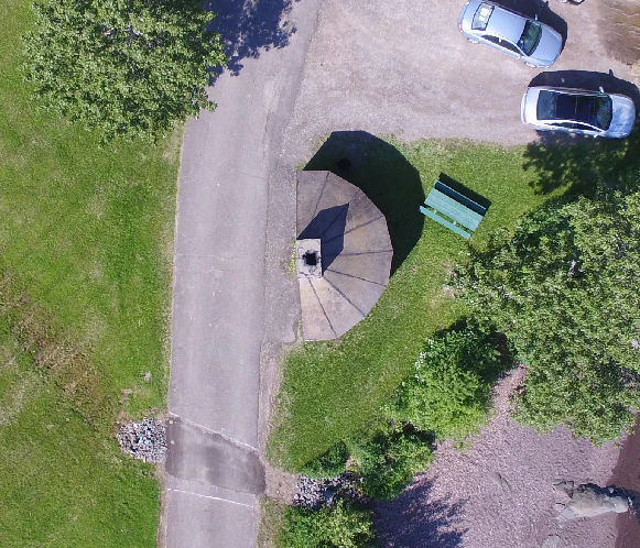
Bowling effect on point cloud over 13,000+ image dataset collected by World Bank Tanzania over the flood prone Msimbasi Basin, Dar es Salaam, Tanzania.
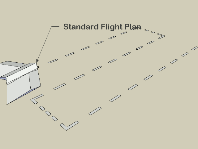
To mitigate this effect, there are a few options but the simplest are as follows: fly two patterns separated by 20°, and rather than having a nadir (straight down pointing) camera, use one that tilts forward by 5°.
As this approach takes longer than traditional imaging, pilots and teams may apply this technique to a smaller area and use the collected data to optimize future flights. OpenDroneMap can generate a calibration file called cameras.json from a small sample flight. The calibration file can be used for future flights, mitigating the bowling effect without sacrificing efficiency.
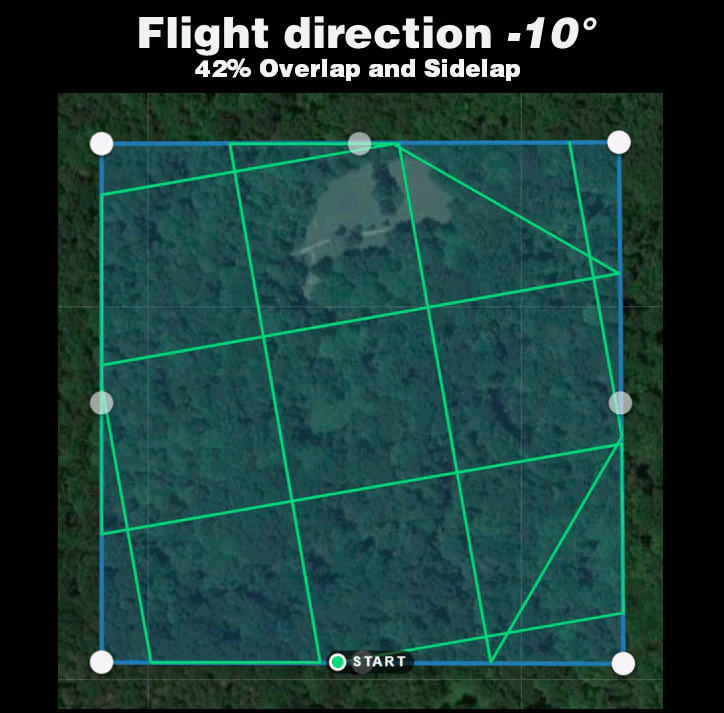
Alternatively, the following experimental method can be applied: fly with much lower overlap, but two crossgrid flights (sometimes called crosshatch) separated by 20° with a 5° forward facing camera.
Crossgrid overlap percentages can be lower than parallel flights. To get good 3D results, you will require 68% overlap and sidelap for an equivalent 83% overlap and sidelap.
To get good 2D and 2.5D (digital elevation model) results, you will require 42% overlap and sidelap for an equivalent 70% overlap and sidelap.
Vertically separated flight lines also improve accuracy, but less so than a camera that is forward facing by 5°.
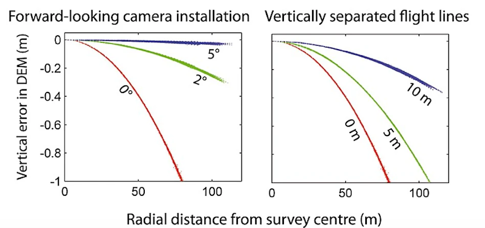
Dari James dan Robson (2014), CC BY 4.0
Using Image Masks
Starting from ODM 2.0 people can supply image masks to inform the software to skip reconstruction over certain areas. This is useful for cases where the sky was accidentally included in the input photos from oblique shots, or simply to limit the reconstruction of a single subject.
To add a mask, simply create a new black and white image of the same dimension as the target image you want to mask (you can use a program such as GIMP to do this). Color in black the areas to exclude from the reconstruction.
Name your file:
<filename>_mask.JPG
For example, DJI_0018.JPG can have a mask by creating a DJI_0018_mask.JPG file and include that in the list of images. You can use .JPG, .PNG, .BMP and .TIF formats for image masks.
Using Singularity
Singularity is another container platform able to run Docker images. Singularity can be run both on local machins and in instances where the user does not have root access. Instances where a user may not have root privlidges include HPC clusters and cloud cluster resources. A container is a single file without anything else to install.
Build Singularity image from Docker image
Singularity can use Docker image to build SIF image.
For latest ODM Docker image (Recommended) :
singularity build --disable-cache -f odm_latest.sif docker://opendronemap/odm:latest
For latest ODM GPU Docker image :
singularity build --disable-cache -f odm_gpu.sif docker://opendronemap/odm:gpu
Using Singularity SIF image
Once you have used one of the above commands to download and create the odm_latest.sif image, it can be ran using singularity. Place your images in a directory named “images” (for example /my/project/images) , then simply run :
singularity run --bind /my/project:/datasets/code odm_latest.sif --project-path /datasets
Like with docker, additional Options and Flags can be added to the command :
singularity run --bind /my/project:/datasets/code \
--writable-tmpfs odm_latest.sif \
--orthophoto-png --mesh-octree-depth 12 --dtm \
--smrf-threshold 0.4 --smrf-window 24 --dsm --pc-csv --pc-las --orthophoto-kmz \
--matcher-type flann --feature-quality ultra --max-concurrency 16 \
--use-hybrid-bundle-adjustment --build-overviews --time --min-num-features 10000 \
--project-path /datasets
ClusterODM, NodeODM, SLURM, with Singularity on HPC
You can write a SLURM script to schedule and set up available nodes with NodeODM for the ClusterODM to be wired to if you are on the HPC. Using SLURM will decrease the amount of time and processes needed to set up nodes for ClusterODM each time. This provides an easier way for user to use ODM on the HPC.
To setup HPC with SLURM, you must make sure SLURM is installed.
SLURM script will be different from cluster to cluster, depending on which nodes in the cluster that you have. However, the main idea is we want to run NodeODM on each node once, and by default, each NodeODM will be running on port 3000. Apptainer will be taking available ports starting from port 3000, so if your node's port 3000 is open, by default NodeODM will be run on that node. After that, we want to run ClusterODM on the head node and connect the running NodeODMs to the ClusterODM. With that, we will have a functional ClusterODM running on HPC.
Here is an example of SLURM script assigning nodes 48, 50, 51 to run NodeODM. You can freely change and use it depending on your system:
#!/usr/bin/bash
#source. bashrc
#SBATCH --partition=8core
#SBATCH --nodelist-node [48,50, 51]
#SBATCH --time 20:00:00

cd SHOME
cd ODM/NodeODM/

#Launch on Node 48
srun --nodes-1 apptainer run --writable node/ &

#Launch on node 50
srun --nodes-1 apptainer run --writable node/ &

#Launch on node 51
srun --nodes=1 apptainer run --writable node/ &
wait
You can check for available nodes using sinfo:
sinfo
Run the following command to schedule using the SLURM script:
sbatch sample.slurm
You can also check for currently running jobs using squeue:
squeue -u $USER
Unfortunately, SLURM does not handle assigning jobs to the head node. Hence, if we want to run ClusterODM on the head node, we have to run it locally. After that, you can connect to the CLI and wire the NodeODMs to the ClusterODMs. Here is an example following the sample SLURM script:
telnet localhost 8080
> NODE ADD node48 3000
> NODE ADD node50 3000
> NODE ADD node51 3000
> NODE LIST
You should always check to make sure which ports are being used to run NodeODM if ClusterODM is not wired correctly.
It is also possible to pre-populate nodes using JSON. If starting ClusterODM from apptainer or docker, the relevant JSON is available at docker/data/nodes.json. Contents might look similar to the following:
[
        {"hostname":"node48","port":"3000","token":""},
        {"hostname":"node50","port":"3000","token":""},
        {"hostname":"node51","port":"3000","token":""}
]
After finish hosting ClusterODM on the head node and finish wiring it to the NodeODM, you can try tunneling to see if ClusterODM works as expected. Open another shell window in your local machine and tunnel them to the HPC using the following command:
ssh -L localhost:10000:localhost:10000 user@hostname
Replace user and hostname with your appropriate username and the hpc address. Basically, this command will tunnel the port of the hpc to your local port. After this, open a browser in your local machine and connect to http://localhost:10000. Port 10000 is where ClusterODM's administrative web interface is hosted at. This is what it looks like:

Here you can check the NodeODMs status and even add or delete working nodes.
After that, do tunneling for port 3000 of the HPC to your local machine:
ssh -L localhost:3000:localhost:3000 user@hostname
Port 3000 is ClusterODM's proxy. This is the place we assign tasks to ClusterODM. Once again, connect to http://localhost:3000 with your browser after tunneling. Here, you can Assign Tasks and observe the tasks' processes.

After adding images in this browser, you can press Start Task and see ClusterODM assigning tasks to the nodes you have wired to. Go for a walk and check the progress.
Development and testing of ODM
Development and testing of code changes can be difficult. The simplest way to do so is modify the code and rebuild docker images from source, much as documented in the README for the ODM repository.
However, having to do a full docker rebuild for each change is time consuming and wasteful. What might be better is to have a dedicated, long running node that allows us to test out changes in near real time.
Fork and clone repository
Set up local NodeODM docker instance
Modify code
Connect to NodeODM instance
Install and use changes
Fork and clone repository
First, let's fork the ODM repo, and checkout a new branch locally that will function as our development branch.
git checkout -b my_clever_new_change
# Switched to a new branch 'my_clever_new_change'
Set up local NodeODM docker instance
Next, we will set up a NodeODM instance with a locally mounted volume that points to our development branch of ODM
docker run -d --restart unless-stopped -p 3000:3000 -v /path/to/cloned/ODM/repository/data:/code opendronemap/nodeodm
Modify code
For our test today, we will attempt to upgrade Ceres Solver to version 2.2.0. Most external libraries like Ceres can be found in the Superbuild directory. In this case we edit SuperBuild/cmake/External-Ceres.cmake, and set it to use version 2.2.0
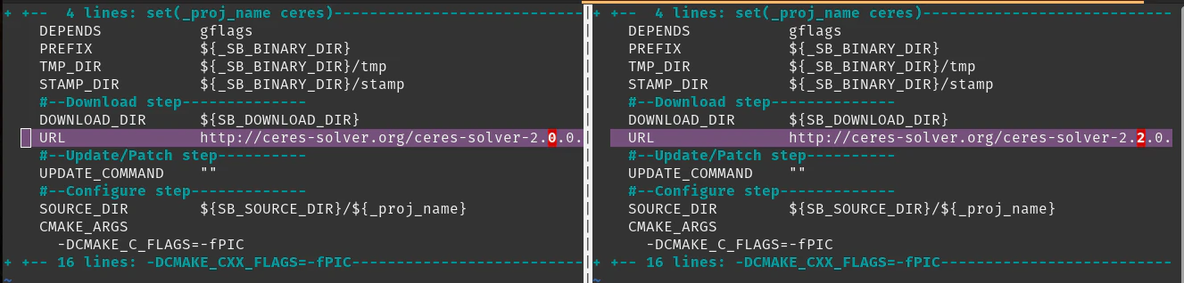
Now that we've made that small, but substantive change, we need to rebuild Ceres on the docker image for testing.
Connect to NodeODM instance
Let us find out our container name, in case we forgot:
docker ps
CONTAINER ID   IMAGE                        COMMAND                  CREATED         STATUS         PORTS                                       NAMES
c997a4c5611b   opendronemap/nodeodm         "/usr/bin/node /var/…"   2 minutes ago   Up 2 minutes   0.0.0.0:3000->3000/tcp, :::3000->3000/tcp   affectionate_yalow
Now that we know the container name, we will connect to that instance using docker exec as follows:
docker exec -it affectionate_yalow bash
Install and use changes
Let us get the environment prepared for our testing:
root@c997a4c5611b:/var/www# cd /code
./configure.sh install
mkdir /code/SuperBuild/build
cd /code/SuperBuild/build
Next we can rebuild Ceres.
cmake ../.
make -j$(nproc) ceres
        ...
-- Up-to-date: /code/SuperBuild/install/include/ceres
-- Up-to-date: /code/SuperBuild/install/include/ceres/internal
-- Installing: /code/SuperBuild/install/include/ceres/internal/config.h
-- Installing: /code/SuperBuild/install/include/ceres/internal/export.h
-- Installing: /code/SuperBuild/install/include/ceres/internal/miniglog/glog/logging.h
-- Installing: /code/SuperBuild/install/lib/cmake/Ceres/CeresTargets.cmake
-- Installing: /code/SuperBuild/install/lib/cmake/Ceres/CeresTargets-release.cmake
-- Installing: /code/SuperBuild/install/lib/cmake/Ceres/CeresConfig.cmake
-- Installing: /code/SuperBuild/install/lib/cmake/Ceres/CeresConfigVersion.cmake
[100%] Completed 'ceres'
[100%] Built target ceres
Success! Now we can either run ODM directly inside this container, use the NodeODM interface to process data, or connect in with OpenDroneMap Desktop for additional testing.
Belajar mengedit dan membantu meningkatkan halaman ini!