Mga Tutoryal
Sa ibaba makikita ang ilang tagubilin para sa ilang mga pang-karaniwang paggamit.
Paglikha ng Mataas na Kalidad ng Orthophotos
Nang walang anumang mga pagpapalit ng parameter, ang ODM ay pumipili ng isang mahusay na kompromiso sa pagitan ng kalidad, bilis at paggamit ng memorya. Kung nais mong makakuha ng mas mataas na kalidad ng mga resulta, kailangan mong magpalit ng ilang mga parameter:
"orthophoto resolution" ay ang resolusyon ng orthophoto sa cm / pixel. Bawasan ang halagang ito para sa isang mas mataas na resulta ng resolusyon.
--mesh-sizeay dapat itaas sa300000-6000at--mesh-octree-depthay dapat itaas ng10-11sa urban areas para maka-create ng magandang building / bubong.
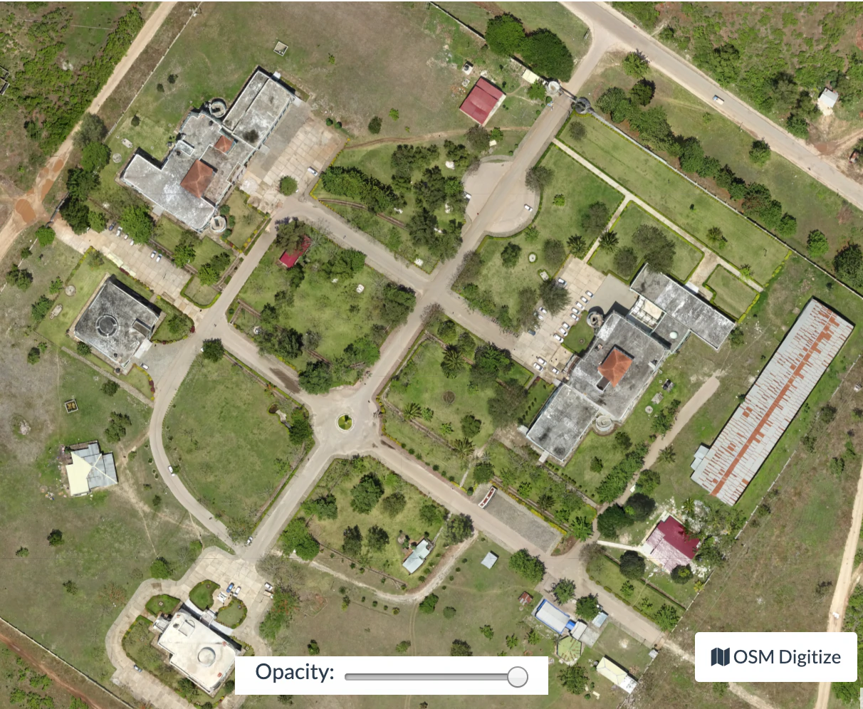
Paglikha ng Digital Elevation Models
By default ODM does not create digital elevation models (DEMs). To create a digital terrain model, make sure to pass the --dtm flag. To create a digital surface model, be sure to pass the --dsm flag.
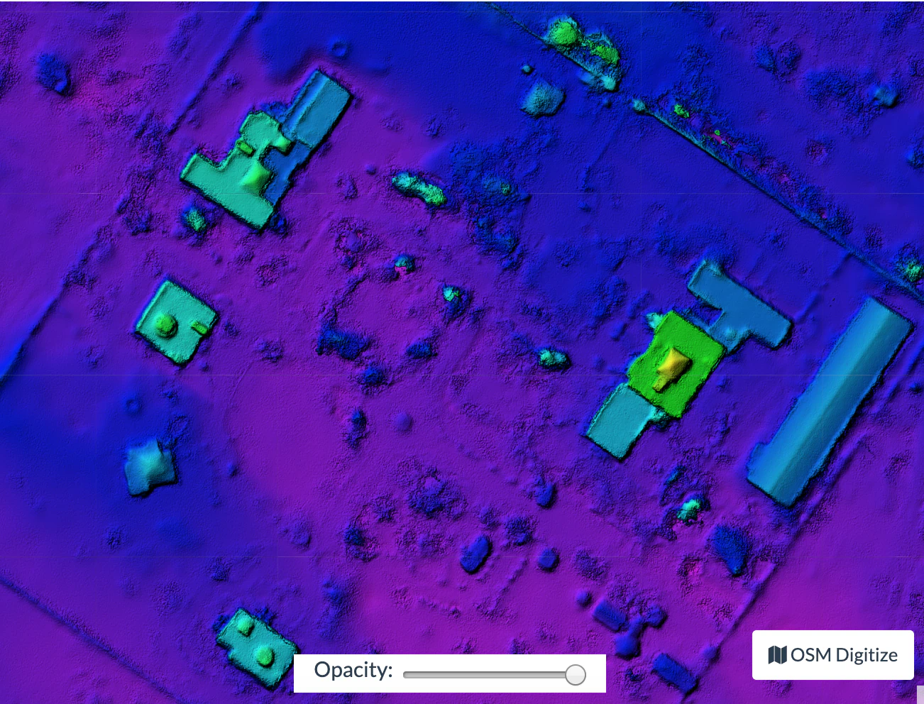
Para sa pag gawa ng DTM, ginagamit ang isang Simple Morphological Filter (smrf) upang mauri ang mga puntos sa nasa lupa kumpara sa wala sa lupa, kung saan ang mga nasa lupa na puntos lamang ang ginagamit. Ang filter na "smrf" ay maaaring kontrolin sa pamamagitan ng maraming mga parameter:
"--smrf-scalar" halaga ng pag-iskala. Taasan ang parameter na ito para sa mga lupain na may maraming pag-iba ng taas.
"--smrf-slope" parametro ng libis, na sukat ng "tolerance ng slope". Taasan ang parametrong ito para sa mga lupain na may maraming pagiiba-iba ng taas. Dapat ang halaga nito ay mas mataas sa 0.1 ngunit hindi tataas sa 1.2.
"--smrf-threshold" bingit ng pagtaas. Itakda ang parametrong ito sa minimong taas (sa yunit na metro) ng mga bagay na wala sa lupa.
"--smrf-window" parametro ng pinakalamaking paikot na sukat (sa yunit na metro) na sukat ng pinakamalaking bagay (gusali, mga puno, atbp.) na aalisin. Dapat itakda sa halagang mas mataas sa 10.
Ang pagpapalit ng mga opsiyon na ito ay nagreresulta ng malaking epekto sa DTMs. Ang pinakamahusay na basahin para mapagkunan ng pinakamahusay na impormasyon ukol sa parametro ng epekto ng output ay ang An improved simple morphological filter for the terrain classification of airborne LIDAR data (Ang PDF ay libre lamang)
Ang --smrf-threshold ang may pinakamalaking impact sa resulta.
Ang SMRF ay mahusay sa pagiwas ng Type I na pagkakamali (maliliit na numero ng ground poins na napagkakamalan bilang non-ground) pero "acceptable" sa pagiwas sa Type II na pagkakamali (malaking numero na non-ground points na napagkakamalan na ground). Ito ay dapat na bigyan importansiya kapag bumubuo ng DTMs na hangarin na gamitin ng biswal, bilang ang mga baga na napagkakamalan na ground ay mukhang artifacts sa resulta ng DTM.
May dalawa pang importanteng parameters na nakakaapekto sa DEM generation:
--dem-resolutionna nagse-set ng output resolution ng DEM raster (cm/pixel)Ang
--dem-gapfill-stepsang tumutukoy sa bilang ng progresibong DEM layer na gagamitin. Para sa urban na eksena na may taas na value na 4-5 ay makakatulong na magresulta ng mas maayos na interpolation sa mga lugar na iniwan na walang laman ng SMRF filter.
Halimbawa kung papaano lumikha ng DTM
docker run -ti --rm -v /my/project:/datasets/code <my_odm_image> --project-path /datasets --dtm --dem-resolution 2 --smrf-threshold 0.4 --smrf-window 24
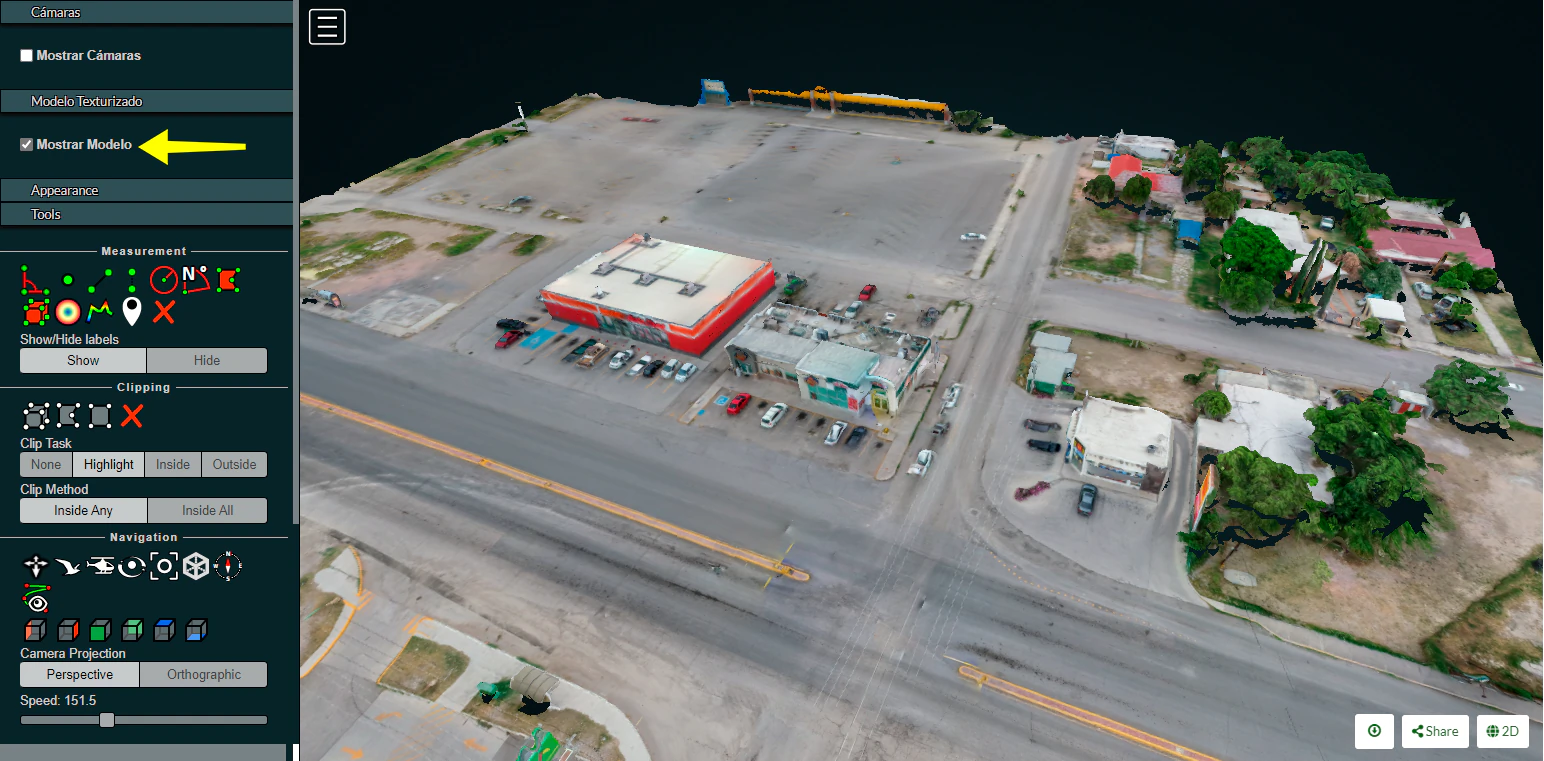
Using Potree 3D viewer module on OpenDroneMap Desktop
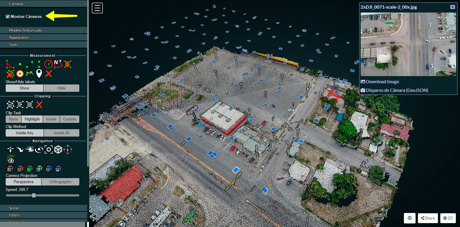
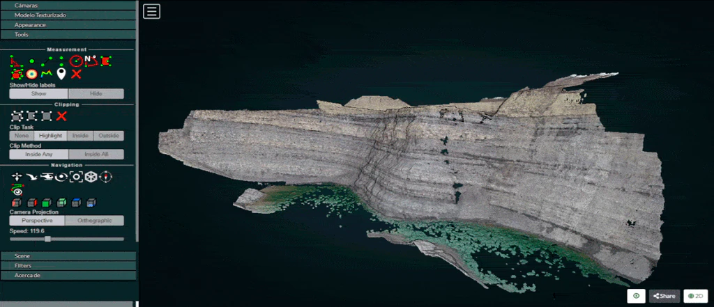
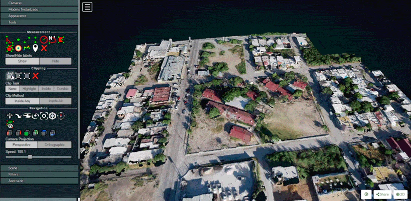
Cameras
Activate this function to display camera positions.
You can also click in the camera icon to display single images in a frame on the upper right corner. A click on the image frame toggles into full screen mode.
Within the image frame there are links to download the image and the GeoJSON camera file.
Textured model
Activate this function to show load the textured model. Depending on the file size and connection speed, it may take several seconds to load.
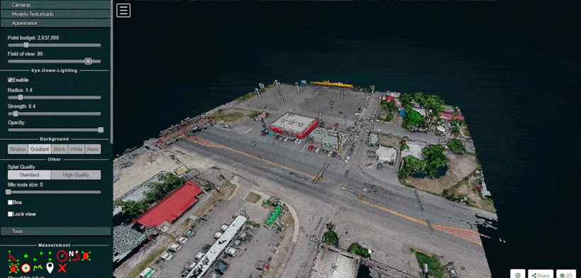
Appearance
Point budget
For both appearance and performance purposes, the point budget on the scene can be managed. Some old and less capable machines would benefit from a 500,000 point budget while most mid-range specs machine are capable of handling 1 to 2 million point budget.
A 5 to 7 million point budget produces a smooth point cloud 3d model, but may result in a high resource demanding process.
Default point budget value is set to 1,000,000.
Field of view
In order to control model elements to be included within the scene the field of view can be adjusted. Default value is set to 60 degrees.
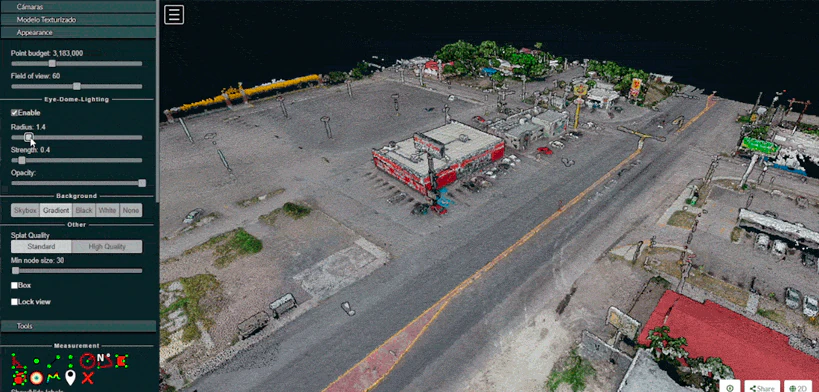
Eye Dome-lighting
The Potree Point Cloud 3d viewer module can implement eye dome-lighting, a lighting model that accentuates the shapes of objects.
Eye Dome-lighting group objects, shade their outlines and enhances depth perception in scientific visualization images. It is useful for recognition and measurement of structures within a model. It can be modified by adjusting Radius, Strength and Opacity.
By default, Eye Dome-Lighting is enabled on Potree 3D viewer, but it can be disabled by clicking on the enable option.
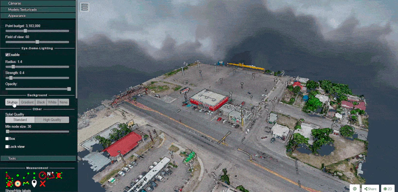
Background
Potree 3D viewer background can be modified. Available options are Skybox / Gradient / Black / White / None
Other
Splat Quality = Splat quality can be adjusted to standard or high quality, to improve the appearance of the model.
Min node size = Min node size option will impact the point density of the nodes represented.
Box = Display the boxes of the nodes.
Lock view = Lock the point cloud view, preventing to load or unload points to the model.
Tools
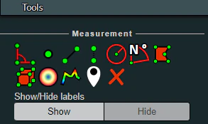
Measurement
Potree 3D viewer module provides several tools for measurement. This tool set consist of 12 elements. It also has controls for showing or hiding the resulting measurement labels.
Measurements are performed by left clicking on the desired points and for some tools right clicking is needed in order to terminate the process.
Angle
This tool measures the tridimensional angle formed by the lines connecting 3 points. To start a measurement, click on the angle icon, then left click on 3 point and the process will be automatically ended. Further information can also be obtained from selecting this element under the scene section.
Point
This tool highlights a selected point and display its XYZ coordinate. To start a measurement, click on the point icon, then click on the desired point and the process will be automatically ended. Further information can also be obtained from selecting this element under the scene section.
Distance
This tool measures the tridimensional distance of the lines connecting a series of points. To start a measurement, click on the distance icon and start clicking on the desired points (two or more). Right click to finish measurement. Further information such as Total length can also be obtained from selecting this element under the scene section.
Height
This tool measures the height or vertical distance between two points. To start a measurement, click on the height icon and then click on the desired two points. The process will be automatically ended. Further information can also be obtained from selecting this element under the scene section.
Circle
This tool measures the radius of a circle formed by three points. To start a measurement, click on the circle icon and then click on the desired two points. The process will be automatically ended. Further information such as Circumference can also be obtained from selecting this element under the scene section.
Azimuth
This tool measures the azimuthal angle of a line. This line is formed by two points selected by the user, the angle is measured in degrees, clockwise from 0 to 360 and starting from the geographical north. To start a measurement, click on the azimuth icon and then click on the desired two points. The process will be automatically ended. Further information can also be obtained from selecting this element under the scene section.
Area
This tool measures the horizontal area formed by a polygon. To start a measurement, click on the area icon and start clicking on the points forming the desired polygon (three or more). Right click to finish measurement. Further information can also be obtained from selecting this element under the scene section.
Volume (cube)
This tool measures the volume formed by a cube. To start a measurement, click on the volume (cube) icon and click on the model to place the cube. It is possible relocate, redimension and rotate the cube using the displayed handlers. Right click to finish measurement. Further information can also be obtained from selecting this element under the scene section.
Volume (sphere)
This tool measures the volume formed by a sphere. To start a measurement, click on the volume (sphere) icon and click on the model to place the sphere. It is possible relocate, redimension and rotate the sphere using the displayed handlers. Right click to finish measurement. Further information can also be obtained from selecting this element under the scene section.
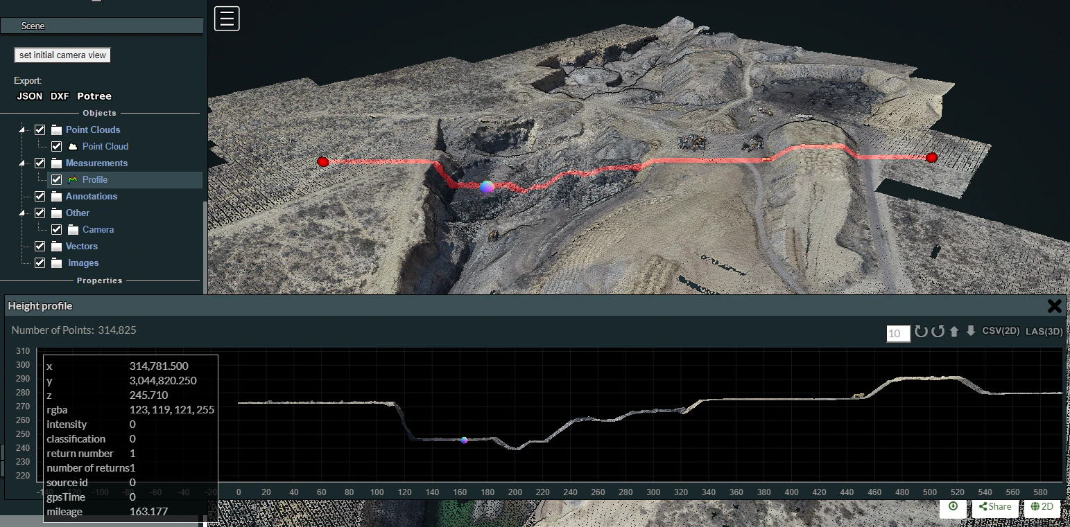
Height profile
This tool creates a height profile formed by a line on the model. To start a measurement, click on the Height profile icon and then form a line on the model by clicking on the desired points (two or more). Right click to finish measurement. Further information and options, such as "Show 2d Profile", can also been obtained from selecting this element under the scene section.
Annotation
This tool creates an annotation label on a highlighted point on the model. To start a measurement, click on the annotation icon and then click on the desired point. The process will be automatically ended. To edit the annotation, select this element under the scene section, then edit Title and Description.
Remove measurements
This tool removes all measurements on the model. To remove all measurement, click on the "Remove measurements" icon.
Clipping
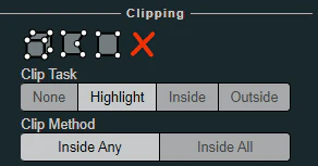
Point cloud can be clipped by selecting an area. Clipping options include None / Highlight / Inside / Outside
To clip a point cloud, click on the volume clip icon, place the cube on the model and relocate, redimension and rotate to contain the desired area. Highlight is set by default as the clipping method. If display only the points contained within the cube click on "Inside", otherwise click on "Outside".
To remove the clipping volume or polygons click on the "Remove all measurements" icon.
Navigation
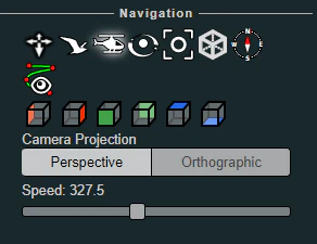
Potree 3D viewer have 4 Navigation controls which define its behavior.
Earth Control
Earth control navigated as anchored to the ground. Mouse left button moves the model horizontally, mouse wheel controls zoom and right button orbits the model.
Fly control
Fly control moves the camera as in birds eye using the keyboard. Keys "W" and "S" moves forward and backwards, respectively and in the direction of the camera, while "A" and "D" moves left and right respectively. Also, the "R" and "F" keys moves the camera up and down. The mouse left button changes the direction of the camera, mouse wheel controls zoom, and right button moves the camera in the XYZ axis.
The speed for these movements can be controlled using the sliding control.
Helicopter control
Helicopter control moves the camera as in an aircraft using the keyboard. Keys "W" and "S" moves forward and backwards, respectively restricted in a horizontal plane, while "A" and "D" moves left and right respectively. Also, the "R" and "F" keys moves the camera up and down. The mouse left button changes the direction of the camera, mouse wheel controls zoom, and right button moves the model in the XY axis.
The speed for these movements can be controlled using the sliding control.
Orbit Control
Orbit Control is the default navigation behavior. The mouse left button orbits the model, the wheel controls zoom and the right button moves the model in the XYZ axis.
Full extent
Full extent button restores the model view.
Navigation cube
Navigation cube displays a wireframe cube containing the model.
Compass
Compass button displays a compass on the upper right corner.
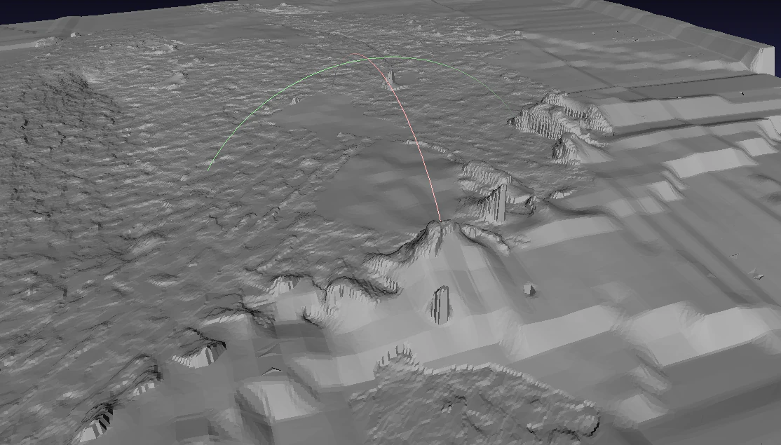
Camera animation
The camera animation button creates a camera animation path. Position of the camera is defined by the points on the green line while the points in the blue line are the location towards the camera is intended to be facing.
To create an animation, adjust the points for the camera locations and camera direction, then select the camera element under the Scene section to create more point, change animation speed or play the animation.
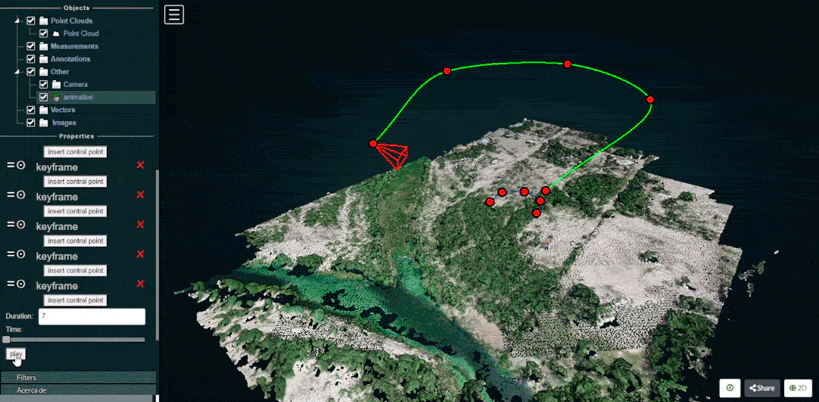
Scene
The Scene section displays a file tree containing all the scene elements. Elements are arranged in six groups, which are Point clouds / Measurements / Annotations / Other / Vector / Images
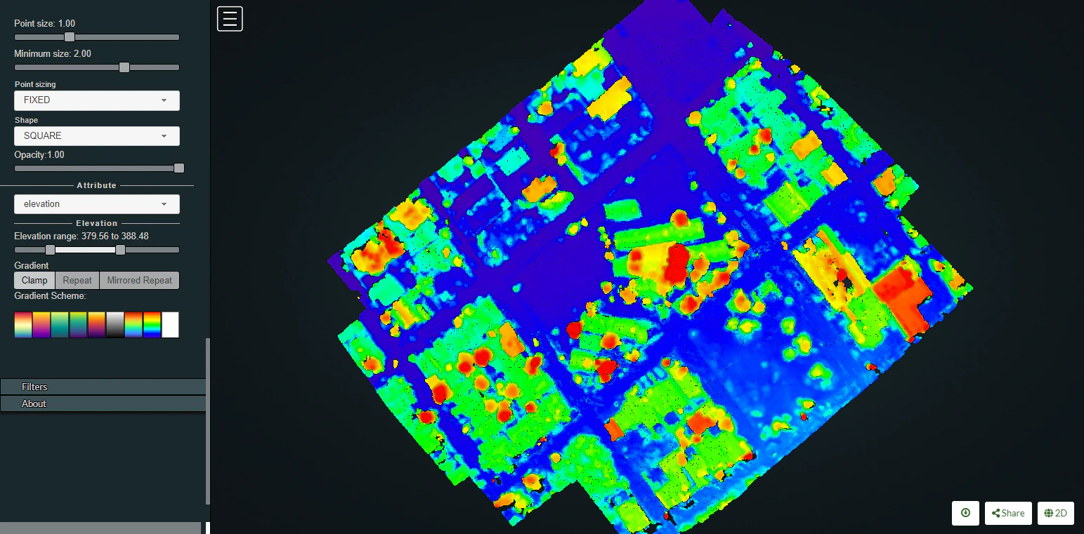
Each element under these groups can be selected to get further information or to control its properties.
For instance, point clouds properties can be modified to show elevation and also the color ramp cam be customized.
Measuring stockpile volume
Fieldwork planning
Weather conditions modify illumination and thus impact the photography results. Best results are obtained with evenly overcast or clear skies. Also look for low wind speeds that allow the camera to remain stable during the data collection process. In order to avoid shadows which on one side of the stockpile can obstruct feature detection and lessen the number of resulting points, always prefer the flights during the midday, when the sun is at the nadir so everything is consistently illuminated. Also ensure that your naked eye horizontal visibility distance is congruent with the planned flight distances for the specific project, so image quality is not adversely impacted by dust, fog, smoke, volcanic ash or pollution.
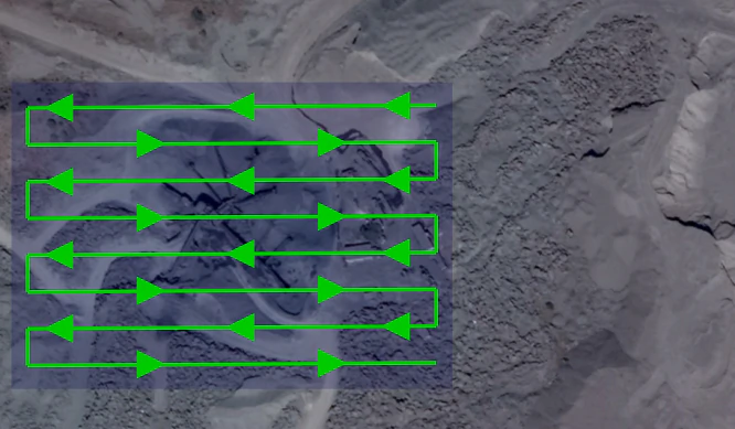
Flight pattern
Most stockpile measurement jobs does not require a crosshatch pattern or angled gimbal as the resting angle of stockpile materials allows the camera to capture the entire stockpile sides. Only some special cases where erosion or machinery operations causes steep angles on the faces of the stockpile would benefit of the crosshatch flight pattern and angled camera gimbal but consider that these additional recognized features come at a cost, (in field labor and processing time) and the resulting improvements are sometimes negligible.
In most of the cases a lawn mower flight pattern is capable of producing highly accurate stockpile models.
Recommended overlap would be between 75% and 80% with a sidelap in the order of 65% to 70%. It is also recommended to slightly increase overlap and sidelap as the flight height is increased.
Flight height
Flight height can be influenced by different camera models, but in a general way and in order to ensure a balance between image quality and flight optimization, it is recommended to be executed at heights 3 to 4 times the tallest stockpile height. So for a 10 meter stockpile, images can be captured at a height of 40 meters. As the flight height is increased, it is also recommended to increase overlap, so for a 40 meter height flight you can set a 65% sidelap and 75% overlap, but for a planned height of 80 meters a 70% sidelap and 80% overlap allowing features to be recognized and properly processed.
GCPs
To achieve accuracy levels better than 3%, the use of GCP’s is advised. Typically 5 distributed GCP are sufficient to ensure accurate results. When placing or measuring GCP, equipment accuracy should be greater than the GSD. Survey grade GNSS and total stations are intended to provide the required millimetric accuracy.
For further information on the use of GCPs, please refer to the Ground Control Points section.
Processing parameters
A highly accurate model can be achieved using OpenDroneMap Desktop high resolution predefined settings. Then you can further adjust some parameters as necessary.
If using ODM, these this reference values can help you configure the process settings.
--dsm: true
--dem-resolution 2.0
--orthophoto-resolution 1.0
--feature-quality high
--pc-quality high
Measuring
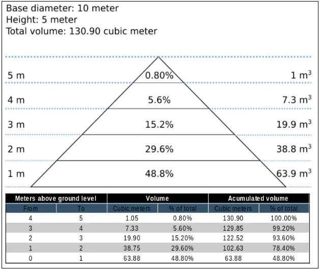
As almost 50% of the material will be found in the first 20% of the stockpile height, special care should be taken in adequately defining the base plane.
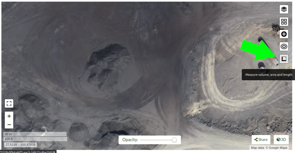
In OpenDroneMap Desktop Dashboard, clic on "view map" to start a 2D view of your project.
Once in the 2D map view, clic on the "Measure volume, area and length" button.
then clic on "Create a new measurement"
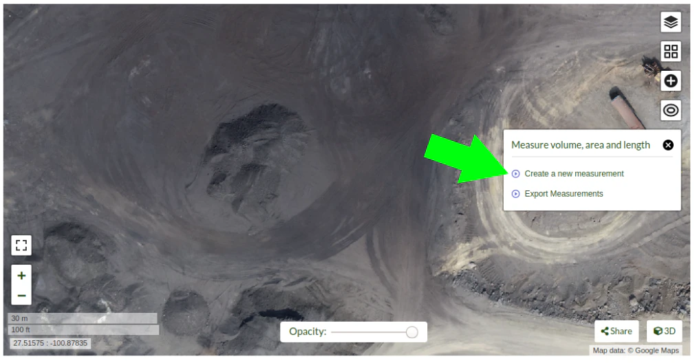
Start placing the points to define the stockpile base plane
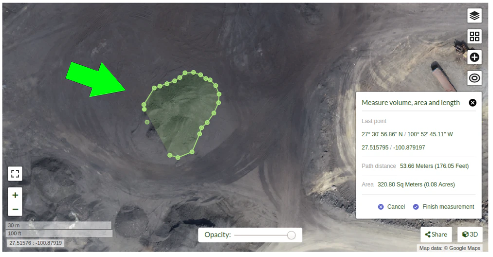
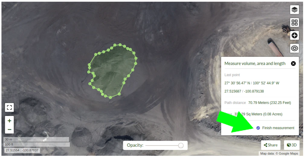
Clic on "Finish measurement" to finish the process.
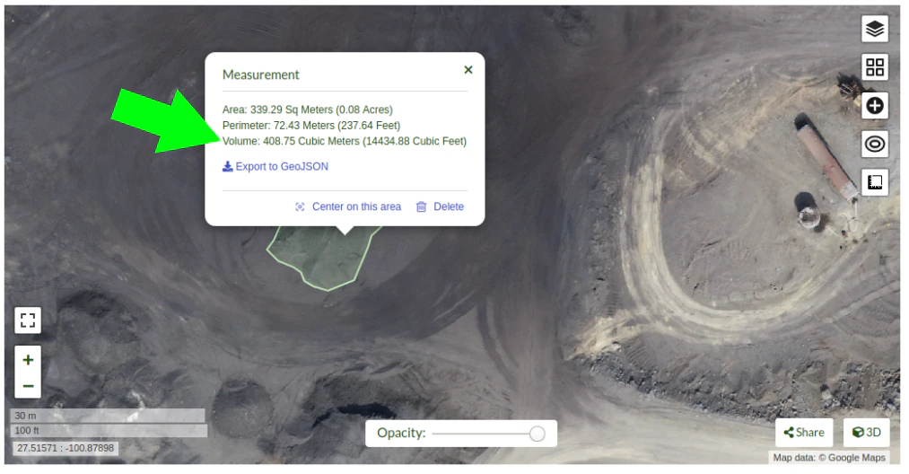
Dialog box will show the message "Computing ..." for a few seconds, and after the computing is finished the volume measurement value will be displayed.
If you are using the command line OpenDroneMap you can use the dsm files to measure the stockpile volumes using other programs.
Also consider that once the limits of the stockpile are set in software like QGis, you will find there are some ways to determine the base plane. So for isolated stockpiles which boundaries are mostly visible, a linear approach can be used. While for stockpiles set in slopes or in bins, the base plane is better defined by the lowest point. Creation of a triangulated 3D surface to define the base plane is advised for large stockpiles. This is also valid for stockpiles paced on irregular surfaces.
Expected accuracy
For carefully planned and executed projects, and specially when GSD is less than 1 cm, the expected accuracy should be in the range of 1% to 2%. The resulting accuracy is comparable to the commercially available photogrammetry software and the obtained using survey grade GNSS equipment.
Using Docker
Bilang maraming gumagamit ang nageemply ng docker para madeply ang OpenDroneMap, makakatulong kapag naiintindihan ang mga basic commands para matanong ang mga pangayayari na ang docker ay nagkakamali. Ang Docker ay isang contained na aplikasyon na ang intensiyon ay mapadali ang pagdeploy ng software independent sa lokal na kapaligiran. Sa lagay na ito, ito ay masasabing pareho sa virtual machines
Ang ilan na simpleng commands ay makakatulong na mapaayos ang experience.
Listing Docker Machines
Masisimulan ito sa paglista ng magagamit na docker machines sa kasalukuyang machine na pinapatakbo:
> docker ps
CONTAINER ID        IMAGE                  COMMAND                  CREATED             STATUS              PORTS                    NAMES
2518817537ce        opendronemap/odm       "bash"                   36 hours ago        Up 36 hours                                  zen_wright
1cdc7fadf688        opendronemap/nodeodm   "/usr/bin/nodejs /va…"   37 hours ago        Up 37 hours         0.0.0.0:3000->3000/tcp   flamboyant_dhawan
Kung nais na makakita ng machines na hindi na tumatakbo ngunit mayroon pa rin, maaaring i-add ang -a flag:
> docker ps -a
CONTAINER ID        IMAGE                  COMMAND                  CREATED             STATUS                    PORTS                    NAMES
2518817537ce        opendronemap/odm       "bash"                   36 hours ago        Up 36 hours                                        zen_wright
1cdc7fadf688        opendronemap/nodeodm   "/usr/bin/nodejs /va…"   37 hours ago        Up 37 hours               0.0.0.0:3000->3000/tcp   flamboyant_dhawan
cd7b9585b8f6        opendronemap/odm       "bash"                   3 days ago          Exited (1) 37 hours ago                            nostalgic_lederberg
e31010c00b9a        opendronemap/odm       "python /code/run.py…"   3 days ago          Exited (2) 3 days ago                              suspicious_kepler
c44e0d0b8448        opendronemap/nodeodm   "/usr/bin/nodejs /va…"   3 days ago          Exited (0) 37 hours ago                            wonderful_burnell
Accessing logs on the instance
Sa paggamit ng CONTAINER ID o ng pangalan, maaaring mapuntahan ang mga logs sa machine na sumusunod:
> docker logs 2518817537ce
Ito ay di hamak na malaki ngunit maaaring gamitin ang | na karakter at iba pang mga tools para kunin ang mga kailangan sa logs. Halimbawa, pwedeng tignan ang log ng mabagal sa pamamagitan ng more command:
> docker logs 2518817537ce | more
[INFO]    DTM is turned on, automatically turning on point cloud classification
[INFO]    Initializing OpenDroneMap app - Mon Sep 23 01:30:33  2019
[INFO]    ==============
[INFO]    build_overviews: False
[INFO]    camera_lens: auto
[INFO]    crop: 3
[INFO]    debug: False
[INFO]    dem_decimation: 1
[INFO]    dem_euclidean_map: False
...
ANg paggamit ng Enter o Space, arrow keys o Page Up o Page Down keys ay makakatulong sa pag-navigate ng logs. Ang maliit na titik Q naman ay ang escape back pabalik ng command line.
We can also extract just the end of the logs using the tail command as follows:
> docker logs 2518817537ce | tail -5
[INFO]    Cropping /datasets/code/odm_orthophoto/odm_orthophoto.tif
[INFO]    running gdalwarp -cutline /datasets/code/odm_georeferencing/odm_georeferenced_model.bounds.gpkg -crop_to_cutline -co NUM_THREADS=8 -co BIGTIFF=IF_SAFER -co BLOCKYSIZE=512 -co COMPRESS=DEFLATE -co BLOCKXSIZE=512 -co TILED=YES -co PREDICTOR=2 /datasets/code/odm_orthophoto/odm_orthophoto.original.tif /datasets/code/odm_orthophoto/odm_orthophoto.tif --config GDAL_CACHEMAX 48.95%
Using band 4 of source image as alpha.
Creating output file that is 111567P x 137473L.
Processing input file /datasets/code/odm_orthophoto/odm_orthophoto.original.tif.
Ang value na -5 ay sinasabihan ang tail command na ibigay ang limang 5 huling linya ng logs.
Command line access to instances
Minsan, kailangan natin na laliman ang pagsusuri sa proseso ng OpenDroneMap. Makakakuha dito ng diretsong command line na daan sa machine. dahil dito, pwede gamitin ang docker exec ng mapasagawa ang bash` command line shell sa machine of interest na sumusunod:
> docker exec -ti 2518817537ce bash
root@2518817537ce:/code#
Ngayon ay naka log-in na tayo sa docker instance at maaari ng suriin ang machine.
Cleaning up after Docker
Ang docker ay may kahina-hinayang na gamit ng space at by default ay hindi naglilinis ng sobrang laman na data at machine kapag ang proseso ay kumpleto na. Ito ay may benepisyo kapag kailangan na puntahan ang proseso na matagal ng terminated pero kinakarga pa rin ang bigat ng nagamit na storage space overtime. Si Maciej Łebkowski ay may 'napakahusay na pangkahalatang-ideya kung papaano aayusin ang sobrang disk usage sa docker <https://lebkowski.name/docker-volumes/>`_.
Paggamit ng ODM para sa low-bandwidth na lokasyon.
Ano ito at para kanino ito?
Via Ivan Gayton's repo.
Ang OpenDroneMap ay hindi naman laging epektibo sa pagset-up locally-ito ay makapagyarihan na machine sa pagproseso ng malalaking datasets ng sa gayon ang cloud machine ay maaaring masagot ang mga tao sa field. Ngunit, bandwidth ang problema sa maraming low-income na setting. Ang kakulangan na ito ay hindi mareresolusyonan agag-agad pero ang mga sumusunod na hakbang ay makatutulong sa pagpapababa ng kailangan na bandwidth para maproseso ang drone imagery datasets sa cloud mula sa African na lokasyon.
Dito ay nagsasaad kami ng nakakalito ngunit maisasagawa na proseso para makagawa ng OPenDronMap cloud machine (hindi CloudODM ito, isa lamang cloud-based instance ng ODM na pwedeng patakbuhin mula sa command line) at gamitin ito para maproseso ang malalaking photo sets. Ito ay nangangailangan nga kaalaman sa Unix command line use, ssh, Digital Ocean account (ang Amazon AWS ay gagana ngunit mga kaunting kaibahan sa set-up), at katamtaman na kaalaman sa general computer literacy. Kung ikaw ay hindi masyadong eksperto at handang pagdaanan ang nakakalito na pagset-up, ang 'CloudODM <https://www.opendronemap.org/cloudodm/>`__ ang dapat pagbasehan.
Ang kabuoan na proseso ay nakatarget sa pagpapalipad ng mga importanteng misyon sa African o kapareho na lokasyon na maghahanap ng ipoproseso na data habang naghihintay ng field setting. Sa madalit sabi, ito ay naglalayon ng trabaho na makababawas sa bandwidth/data transfer, kesa sa simlpeng pagpapatakbo lamang ng ODM.
Steps
Install
Gumawa ng Digital Ocean droplet na may 4GB na RAM. Ito ay magkakapresyo ng $20/month. Hindi sapat ang 4GB na RAM at ang installation ay siguradong hindi matutuloy. Kapag ang ODM na proseso ay pinapatakbo, ito ay nire-resize sa mas malaki-at mas mahal-na cloud machine pero habang ito ay pinapatakbo, maaari na pababain sa pangalawang pinakamura na drooplet na nagkakahalaga ng $10/month (pinakamura na droplet na nasa $5/month, may kasama na maliit na drive na hindi na pwedeng magdownsize pabalik dito).
Dapat ay Ubintu 18.04 na instansiya para makasiguro sa dependency compatibility.
Gumawa ng user na may pribelehiyong sudo. Digital Ocean’s insanely good documentation ay makakatulong na alamin ito. Sa aming kaso, nagset-up kami ng user na may pangalan na
odm, para kumonekta via sa command nassh odm@xxx.xxx.xxx.xxx(kung saan ang x's ay IPv4 na address ng iyong server). Kung nais na sundan ito, gamitin ang username naodm; tapos ang install path dapat ay/home/odm/ODM/at makakapareho ang mga halimbawa sa dokumento na ito.Magpatuloy sa pagpapasagawa ng
sudo apt updateatsudo apt upgradepara masigurado na ang server ay may updates. Siguraduhin na nasa Ubuntu 18.04.
Download and install ODM on it from the ODM Github with the following commands:
git pull https://github.com/OpenDroneMap/ODM.git
cd ODM
bash configure.sh install
Kapag ito ay nagawa mo na sa default home faulder ng user (i.e.``odm``) ang daan papunta sa paginstall ay
/home/odm/ODM(abbreviated as~/ODM/).May mga elemento na pangkalikasan na kelangan isaayos. Buksan ang ~/.bashrc file sa iyong machine at idagdag ang 3 linya sa huli (From the ODM github). Ang file ay pwedeng buksan sa
nano ~/.bashrc(o sakahit anong text editor na ginagamit sa halip ng nano). Siguraduhin na napalitan ang/home/odm/ng tama na path papunta sa lokasyon kung saan inextract ang OpenDroneMap kung hindi nagawa ang mga hakbang ng eksaktong katulad ng mga nasa halimbawa (halimbawa ay ang paggamit ng ibang username sa server setup):
export PYTHONPATH=$PYTHONPATH:/home/odm/ODM/SuperBuild/install/lib/python2.7/dist-packages
export PYTHONPATH=$PYTHONPATH:/home/odm/ODM/SuperBuild/src/opensfm
export LD_LIBRARY_PATH=$LD_LIBRARY_PATH:/home/odm/ODM/SuperBuild/install/lib
Alalahanin na ang ODM github readme ay naglalaman ng kaunting kamalian, ang pangalan ng direktoryong pang-install ay ODM, hindi OpenDroneMap (Makikita ito kapag kinumpara ag mga iinstruksiyon sa taas sa mga instruksiyon sa ODM GitHub).
Para maiwasan ang pag-crash kung saan ang split-merge na proseso ay hindi na ma-locate ang sarili nitong executable, dinaragdag natin ang mga sumusunod na linya
~/.bashrc(i-adjust ang paths kung may makita na kakaiba sa aming halimbawa):
export PYTHONPATH=$PYTHONPATH:/home/odm/ODM/
export PATH=$PATH:/home/odm/ODM/
Ngayon, kakailanganin mo ng pangalawang cloud hard drive (“Volume” in Digital Ocean jargon) na may sapat na laki para sa iyong proyekto. Ang pamantayan ay 10 beses ng laki iyong raw image set; ay mayroon 100GB na image set at set-up na 1000GB volume (kapag ito ay napaandar na, dapat ay makapagbawas na ng mga mamahalin na drive capacity, ito ay kailangan para matapos ang proseso). Iset-up ang volume at i-attach ito sa droplet at 'ayusin ang mount point <https://www.digitalocean.com/docs/volumes/how-to/mount/>`__ (sa halimbawa na ito, ise-set natin sa
/mnt/odmdata/).
Prep data and project
Ngayon, i-push ang mga imahe sa server. Maaaring gamitin ang Now push your images onto the server. You can use Secure Copy (scp) like so:
scp -r /path/to/my/imagefolder odm@xxx.xxx.xxx.xxx:/mnt/odmdata/.
Istraktura ng direktoryo
Nirerequire ng ODM na iset-up ang direktoryo sa machine. ANg kritikal ay ang install folder (kung ininstall mo katulad ng nasa taas, /home/odm/ODM/) at ang project folder (i.e. /mnt/odmdata/myproject/)
Ang ODM settings.yaml file ay nag-specify ng isang parent directory na naglalaman ng lahat ng proyekto. Ito ang nangyayari sa path line ng proyekto ng settings.yaml file (medyo nakakalito ito ngunit ito ang parent diirectory ng mga indibidwal na direktoryo ng proyekto na tinutukoy sa project name parameter kapag tinatawagan ang ODM). Ang edit settings.yaml at ang set ng project_path parameter sa (ayon sa halimbawa na set-up)
/mnt/odmdata/, na sa kaso na ito ay pinupunto ang volume na nilikha. Ang Indibidwal na direktoryo ng proyekto ay nilikha sa loob nito.Individual project directories, i.e.
/mnt/odmdata/myproject/contain the gcp_list.txt file, the image_groups.txt file, and the images folder for each project.Ang folder ng imahe, i.e.
/mnt/odmdata/myproject/images/ay naglalaman ng lahat ng imahe. Kapag sinet-up ito ng ganon, hindi marere-copy ang mga imahe dahil ito ay nasa direktoryo na kung saan gusto sila ilagay ng ODM.I-modify ang settings.yaml para matukoy ang parent directory ng project folder (sa kaso na ito ang Volume na nilikha,
/mnt/odmdata/). Siguraduhin na ang mga imahe ay nasa tamang lugaw, i.e./mnt/odmdata/myproject/imagesat ang ibang ancillary files/mnt/odmdata/myproject/imagesay nasa root folder/mnt/odmdata/myproject/Kung ang mga imahe mo ay nasa hiwalay na folder para sa indibidwal na AOI blocks or flights (na kadalasan ay nangyayari kapag ang iyong pamamahala ay organisado), pwedeng gumawa ng image_groups.txt file na may incantation na
for i in *; do cd $i; for j in *; do echo "$j $i" >> ../$i.txt; done; cd ../; done;atcd ../,for i in myproject/*.txt; do cat $i >> image_groups.txt; done;. Ito ay makakabuo ng file na may tamang istraktura: listahan ng mga imahe at "group name" pagkatapos ng bawat isa (na sa kaso na ito madalas ay pangalan ng folder na pinanggalingan nito). Ilagay ang lahat ng image files sa isang direktoryo na tatawagin na images sa project root dir (so/mnt/odmdata/myproject/images/). Ang image_groups.txt file ay papayagan ng ODM na bantayan ang mga imahe na na kasapi ng kaparehong batch, kahit na sila ay nasa iisang direktoryo lamang.
I-resize ang droplet, hatakin ang pin at i-proseso ito.
Patayin at ire-size ang machine sa tamang bilang ng CPUs at laki ng memory. Ginagamit namin ang memory-optimized machine na may 24 na dedicated vCPUs at 192GB na RAM (na nagkakahalaga ng $1.60/hr-na dumaragdag ng mabilis, ito ay nasa $1000/month). I-restart at magsimula agad para hindi masayang nag mahal na big-droplet time.
i-launce ang ODM na proseso gamit ang ssh at nohup (para kahit ikaw ay maputol, magtutuloy-tuloy ang proseso)
Pwedeng gamitin ang GNU screen para masimulan ang proseso mula sa screen session na hindi hihinto kung ang konesyon mo ay hindi masisira; I-launch ang
screen, at gamitin ang<ctrl> a <ctrl> dpara humiwalay atscreen -rpara kumabit ulit. Ngunit ang paggamit ng screen ay hindi makakapagbigay ng log file ng lahat ng console output maliban kung may gagawin na partikular para ito ay makuhanan. Ang nohup ay nagbibigay ng file na kasama ang lahat n g console output kasama na ang error messages ng libre.Tandaan: as of 2020-03 ang normal na incantation na
python run.py -i /path/to/image/folder project_nameay mukhang hindi gumagana; ang-ior--imageparameter ay nagdudulot ng kakaibang error. So hindi na ginagamit ang -i parameter, ayt umaasa na lamang sa project directory line sa settings.yaml file para iderekta ang ODM sa tamang lugar. Ngayon ay gumagamit (kasama ang split-merge):
nohup python run.py myproject --split 1 --split-overlap 0 --orthophoto-resolution 5 --dem-resolution 15 --pc-las --dsm
Tinuturo ang ODM sa folder (sa halimbawa na ito)
/mnt/odmdata/myproject/. Sa kondisyon na image_groups.txt at ang image_groups.txt ay nasa folder na ito, ang mga imahe ay nasa/mnt/odmdata/myproject/images/, at ang project path sa settings.yaml ay/mnt/odmdata/hindi masasayang ang oras at ang ispasyo sa pagkopya ng imahe.Tandaan na ina-assume dito na ikaw ay meroong image_groups.txt file. Kung wala, itong
-split-overlap 0ay paniguradong masisira ang lahat at ang--split 1naman ay literal na sapalarang numero lamang na hindi papansinin matapos ang image_groups.txt file ay ma-load (normal na kinokontrol nito ang dami ng grupo ng imahe na hinihiwalay nito, pero sa kaso na ito ay ating inaasahan na ang mga imahe ay nakagrupo na). Kung ikaw ay walang malaki na dataset (>1000 na imahe), tanggalin ang--splitat--split-overlapna opsiyon.Sundan ang progreso gamit ang tail (para malaman kapag tapos na)
tail -f nohup.out
Kailangan bantayan ang htop (para mas matantsa ang konsumo ng sa susunod, ikaw ay magspin-up lamang ng machine base sa pangangalangan)
Matapos ang lahat (assuming na ikaw ay nagsurvive ng ganoon katagal)
Kapag tapos na ang proseso, patayin ang machine at ire-size ito pabalik sa inexpensive minimum capacity.
Simulan ang machine back up at log in via ssh.
Kung gusto makatipid sa download bandwidth, pwedeng icompress ang orthophoto gamit ang GDAL. Wag magdagdag ng overviews, gawin ito sa iyong lokal na machine para maiwasan ang pagpapalaki ng file bago ito i-download.
gdal_translate -co COMPRESS=JPEG -co PHOTOMETRIC=YCBCR -co TILED=YES -b 1 -b 2 -b 3 -mask 4 --config GDAL_TIFF_INTERNAL_MASK YES /path/to/original/filename.extension /path/to/output.tif
Magdownload gamit ang:
scp odm@xxx.xxx.xxx.xxx:/mnt/odmdata/myproject/odm_orthophoto/odm_orthophoto.tif(o i-grab ang compressed na bersiyon na ginawa mo sa huling hakbang)Kapag nakuha na ang file sa iyong lokal na computer, gamitin ang QGIS para magdagdag ng overviews (“pyramids”) o gamitin ang GDAL command gdaladdo -r average /path/to/image.tif 2 4 8 16 32 64 128 256 512 1024`.
Maaaring i-archive ang odm_texturing, odm_georeferencing, at odm-dem folders gamit ang tar ng mas mapadali ang pagdownload ng isang piraso (at maaaring mas maliit).
tar -zcvf archivename /path/to/folder
Advanced
Pag-kalibrate ng Camera
Ang pag-calibrate ng camera ay isang malaking hamon sa mga pangkaraniwang camera. Ang mga pagbabago sa temperatura, mga vibrations, pokus, at iba pang mga kadahilanan ay maaaring makaapekto sa mga hango na mga parameter na may malaking epekto sa resultang data. Ang awtomatikong o pag-calibrate sa sarili ay posible at mas mainam sa mga drone flights, ngunit depende sa pattern ng flight, ang awtomatikong pagkakalibrate ay maaaring hindi mag-alis ng lahat ng pagbaluktot sa mga nagresultang produkto. Sa papel nina James at Robson (2014) na "Ang pagpapalit ng sistematikong error sa mga topographic models na nagmula sa UAV at ground ‐ based image networks <https://onlinelibrary.wiley.com/doi/full/10.1002/esp.3609> ay nagpapakita kung paano mabawasan ang pagkabaluktot.
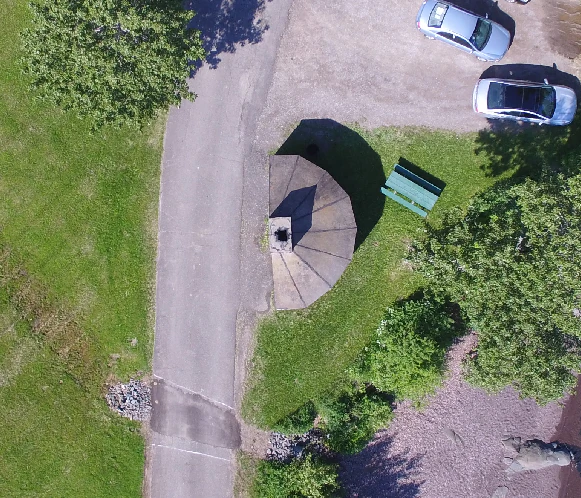
Ang epekto ng "Bowling" sa point cloud ng mahigit "13,000+ imahe na nakalap ng World Bank Tanzania sa bahaing lugar ng Msimbasi, Basin, Dar es Salaam, Tanzania.
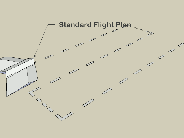
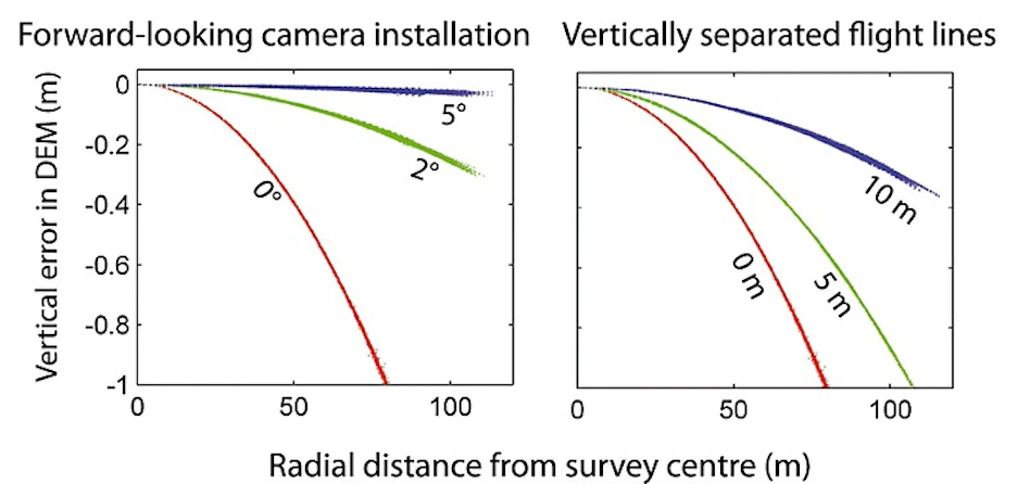
Upang pagaanin ang epekto na ito, may ilang mga pagpipilian ngunit ang pinakasimple ay ang mga sumusunod: lumipad ng dalawang pattern na pinaghihiwalay ng 20°, at sa halip na magkaroon ng isang nadir (tuwid at pababang pagturo) camera, gumamit ng isa na nakakiling sa harap ng 5°.
As this approach takes longer than traditional imaging, pilots and teams may apply this technique to a smaller area and use the collected data to optimize future flights. OpenDroneMap can generate a calibration file called cameras.json from a small sample flight. The calibration file can be used for future flights, mitigating the bowling effect without sacrificing efficiency.
Bilang kahalili, ang sumusunod na pamamaraan ng eksperimento ay maaaring gawin: lumipad na may mas mababang overlap, ngunit dalawang flight ng crossgrid (kung minsan ay tinatawag na crosshatch) na pinaghiwalay ng 20° na may 5° pasulong na nakaharap na camera.
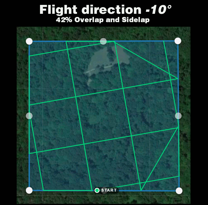
Ang mga porsyento na overlap ng crossgrid ay maaaring mas mababa kaysa sa mga kahilera na flight. Upang makakuha ng mahusay na mga resulta ng 3D, kakailanganin ang 68% na magkakapatong at sidelap para sa katumbas na 83% na magkakapatong at sidelap.
Upang makakuha ng magandang resulta ng 2D at 2.5D (digital elevation model), kakailanganin ang 42% na magkakapatong at sidelap para sa isang katumbas na 70% na magkakapatong at sidelap.
Ang mga magkakahiwalay na linya ng flight ay nagpapabuti din sa kawastuhan, ngunit mas kaunti kaysa sa isang kamera na pasulong na hinaharap ng 5°.
Mula kay James at Robson (2014), 'CC BY 4.0 <https://creativecommons.org/licenses/by/4.0>_
Using Image Masks
Starting from ODM 2.0 people can supply image masks to inform the software to skip reconstruction over certain areas. This is useful for cases where the sky was accidentally included in the input photos from oblique shots, or simply to limit the reconstruction of a single subject.
To add a mask, simply create a new black and white image of the same dimension as the target image you want to mask (you can use a program such as GIMP to do this). Color in black the areas to exclude from the reconstruction.
Name your file:
<filename>_mask.JPG
For example, DJI_0018.JPG can have a mask by creating a DJI_0018_mask.JPG file and include that in the list of images. You can use .JPG, .PNG, .BMP and .TIF formats for image masks.
Using Singularity
Singularity is another container platform able to run Docker images. Singularity can be run both on local machins and in instances where the user does not have root access. Instances where a user may not have root privlidges include HPC clusters and cloud cluster resources. A container is a single file without anything else to install.
Build Singularity image from Docker image
Singularity can use Docker image to build SIF image.
For latest ODM Docker image (Recommended) :
singularity build --disable-cache -f odm_latest.sif docker://opendronemap/odm:latest
For latest ODM GPU Docker image :
singularity build --disable-cache -f odm_gpu.sif docker://opendronemap/odm:gpu
Using Singularity SIF image
Once you have used one of the above commands to download and create the odm_latest.sif image, it can be ran using singularity. Place your images in a directory named “images” (for example /my/project/images) , then simply run :
singularity run --bind /my/project:/datasets/code odm_latest.sif --project-path /datasets
Like with docker, additional Options and Flags can be added to the command :
singularity run --bind /my/project:/datasets/code \
--writable-tmpfs odm_latest.sif \
--orthophoto-png --mesh-octree-depth 12 --dtm \
--smrf-threshold 0.4 --smrf-window 24 --dsm --pc-csv --pc-las --orthophoto-kmz \
--matcher-type flann --feature-quality ultra --max-concurrency 16 \
--use-hybrid-bundle-adjustment --build-overviews --time --min-num-features 10000 \
--project-path /datasets
ClusterODM, NodeODM, SLURM, with Singularity on HPC
You can write a SLURM script to schedule and set up available nodes with NodeODM for the ClusterODM to be wired to if you are on the HPC. Using SLURM will decrease the amount of time and processes needed to set up nodes for ClusterODM each time. This provides an easier way for user to use ODM on the HPC.
To setup HPC with SLURM, you must make sure SLURM is installed.
SLURM script will be different from cluster to cluster, depending on which nodes in the cluster that you have. However, the main idea is we want to run NodeODM on each node once, and by default, each NodeODM will be running on port 3000. Apptainer will be taking available ports starting from port 3000, so if your node's port 3000 is open, by default NodeODM will be run on that node. After that, we want to run ClusterODM on the head node and connect the running NodeODMs to the ClusterODM. With that, we will have a functional ClusterODM running on HPC.
Here is an example of SLURM script assigning nodes 48, 50, 51 to run NodeODM. You can freely change and use it depending on your system:
#!/usr/bin/bash
#source. bashrc
#SBATCH --partition=8core
#SBATCH --nodelist-node [48,50, 51]
#SBATCH --time 20:00:00

cd SHOME
cd ODM/NodeODM/

#Launch on Node 48
srun --nodes-1 apptainer run --writable node/ &

#Launch on node 50
srun --nodes-1 apptainer run --writable node/ &

#Launch on node 51
srun --nodes=1 apptainer run --writable node/ &
wait
You can check for available nodes using sinfo:
sinfo
Run the following command to schedule using the SLURM script:
sbatch sample.slurm
You can also check for currently running jobs using squeue:
squeue -u $USER
Unfortunately, SLURM does not handle assigning jobs to the head node. Hence, if we want to run ClusterODM on the head node, we have to run it locally. After that, you can connect to the CLI and wire the NodeODMs to the ClusterODMs. Here is an example following the sample SLURM script:
telnet localhost 8080
> NODE ADD node48 3000
> NODE ADD node50 3000
> NODE ADD node51 3000
> NODE LIST
You should always check to make sure which ports are being used to run NodeODM if ClusterODM is not wired correctly.
It is also possible to pre-populate nodes using JSON. If starting ClusterODM from apptainer or docker, the relevant JSON is available at docker/data/nodes.json. Contents might look similar to the following:
[
        {"hostname":"node48","port":"3000","token":""},
        {"hostname":"node50","port":"3000","token":""},
        {"hostname":"node51","port":"3000","token":""}
]
After finish hosting ClusterODM on the head node and finish wiring it to the NodeODM, you can try tunneling to see if ClusterODM works as expected. Open another shell window in your local machine and tunnel them to the HPC using the following command:
ssh -L localhost:10000:localhost:10000 user@hostname
Replace user and hostname with your appropriate username and the hpc address. Basically, this command will tunnel the port of the hpc to your local port. After this, open a browser in your local machine and connect to http://localhost:10000. Port 10000 is where ClusterODM's administrative web interface is hosted at. This is what it looks like:

Here you can check the NodeODMs status and even add or delete working nodes.
After that, do tunneling for port 3000 of the HPC to your local machine:
ssh -L localhost:3000:localhost:3000 user@hostname
Port 3000 is ClusterODM's proxy. This is the place we assign tasks to ClusterODM. Once again, connect to http://localhost:3000 with your browser after tunneling. Here, you can Assign Tasks and observe the tasks' processes.

After adding images in this browser, you can press Start Task and see ClusterODM assigning tasks to the nodes you have wired to. Go for a walk and check the progress.
Development and testing of ODM
Development and testing of code changes can be difficult. The simplest way to do so is modify the code and rebuild docker images from source, much as documented in the README for the ODM repository.
However, having to do a full docker rebuild for each change is time consuming and wasteful. What might be better is to have a dedicated, long running node that allows us to test out changes in near real time.
Fork and clone repository
Set up local NodeODM docker instance
Modify code
Connect to NodeODM instance
Install and use changes
Fork and clone repository
First, let's fork the ODM repo, and checkout a new branch locally that will function as our development branch.
git checkout -b my_clever_new_change
# Switched to a new branch 'my_clever_new_change'
Set up local NodeODM docker instance
Next, we will set up a NodeODM instance with a locally mounted volume that points to our development branch of ODM
docker run -d --restart unless-stopped -p 3000:3000 -v /path/to/cloned/ODM/repository/data:/code opendronemap/nodeodm
Modify code
For our test today, we will attempt to upgrade Ceres Solver to version 2.2.0. Most external libraries like Ceres can be found in the Superbuild directory. In this case we edit SuperBuild/cmake/External-Ceres.cmake, and set it to use version 2.2.0
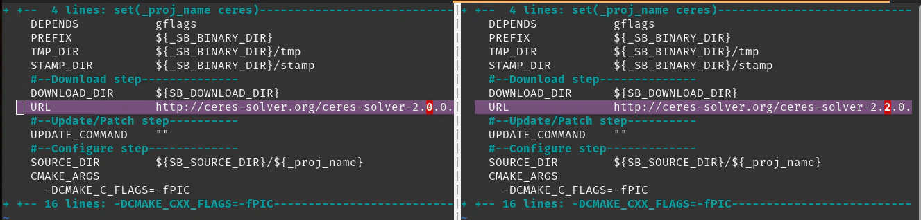
Now that we've made that small, but substantive change, we need to rebuild Ceres on the docker image for testing.
Connect to NodeODM instance
Let us find out our container name, in case we forgot:
docker ps
CONTAINER ID   IMAGE                        COMMAND                  CREATED         STATUS         PORTS                                       NAMES
c997a4c5611b   opendronemap/nodeodm         "/usr/bin/node /var/…"   2 minutes ago   Up 2 minutes   0.0.0.0:3000->3000/tcp, :::3000->3000/tcp   affectionate_yalow
Now that we know the container name, we will connect to that instance using docker exec as follows:
docker exec -it affectionate_yalow bash
Install and use changes
Let us get the environment prepared for our testing:
root@c997a4c5611b:/var/www# cd /code
./configure.sh install
mkdir /code/SuperBuild/build
cd /code/SuperBuild/build
Next we can rebuild Ceres.
cmake ../.
make -j$(nproc) ceres
        ...
-- Up-to-date: /code/SuperBuild/install/include/ceres
-- Up-to-date: /code/SuperBuild/install/include/ceres/internal
-- Installing: /code/SuperBuild/install/include/ceres/internal/config.h
-- Installing: /code/SuperBuild/install/include/ceres/internal/export.h
-- Installing: /code/SuperBuild/install/include/ceres/internal/miniglog/glog/logging.h
-- Installing: /code/SuperBuild/install/lib/cmake/Ceres/CeresTargets.cmake
-- Installing: /code/SuperBuild/install/lib/cmake/Ceres/CeresTargets-release.cmake
-- Installing: /code/SuperBuild/install/lib/cmake/Ceres/CeresConfig.cmake
-- Installing: /code/SuperBuild/install/lib/cmake/Ceres/CeresConfigVersion.cmake
[100%] Completed 'ceres'
[100%] Built target ceres
Success! Now we can either run ODM directly inside this container, use the NodeODM interface to process data, or connect in with OpenDroneMap Desktop for additional testing.
Learn to edit and help improve this page!